This information will be updated regularly, last updated 22 February 2025
Work in Progress
Monitoring
I’m using a combination of Open Energy Monitor and Home Assistant to display and record my heating’s data.
The above graph consolidates my boilers data to give an overall efficiency and is linked to my configuration on emoncms.org.
The Open Energy project is primarily focused on monitoring to get the best Coefficient of Performance (COP) out of your system, this is more applicable to Heat Pumps which can have efficiencies of over 500% rather than Gas Boilers which will never be 100% efficient, however, its good to know how its performing and if I can improve.
The feed data used to compile and compute the overall efficiency:
- Outside temperature
- Room temperature
- Target temperature
- Boiler actual power usage
- Boiler cumulative power usage
- Gas actual usage
- Central heating – on or off
- Domestic hot water – on or off
- Heatmeter
- – Cumulative energy
- – Return temperature
- – Flow temperature
- – Power
- – Flow rate
- – Power
- – Flow temperature
- – Return temperature
- – Cumulative energy
- Heatmeter
My Controls
I use HIVE to schedule my heating and hot water, all radiators have independently controlled HIVE Thermostatic Radiator Valves (TRVs).
The current setup is that all the radiator TRVs are set to 23oC for temperature overshoot prevention and the Hall wall mounted thermostat is set to 21.5oC to control the on/off signal to the boiler.
The idea of this configuration is to keep the house at a comfortable ambient temperature using a low boiler temperature flow to the radiators, these radiators have been sized to map the rooms heat losses.

I still have some work with regards to radiator balancing and tweaking the flow temperature.
Domestic hot water recharge flow temperature is independent from the heating, referred to as Priority Domestic Hot Water (PDHW) and will have a flow temperature of 80oC, during this time the flow to the radiators will be off.
The CIBSE domestic heating design guide for room temperatures was followed, however, as no ground floor door is closed and we don’t have a door closed to the stairs, heat certainly rises and room temperature overshoot is inevitable.
An Opentherm hall thermostat would possibly reduce temperature overshoot, but if I can strike the correct balance with flow temperature and weather compensation slope settings, I should be near enough.
One thing to be careful of with low flow temperature radiators, is that there is no sudden rush of heat, its all very steady to match the room losses, if the room is cold, it will take time to warm up, so best keep it at a reasonable set-back temperature when the system is off.
A set-back temperature is a point at which the heating will resume even though it is outside of the programmed heat schedule, in my case 17oC.
Weather Compensation
Very early days yet and I’m trying to get to grips with the weather compensation slope to give me the most efficient return.
My slope settings vary between 12 and 13:
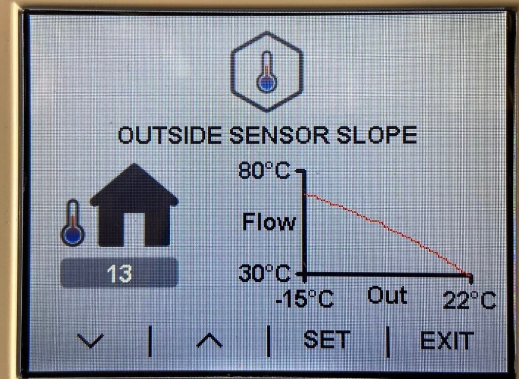
The efficiency of this is:
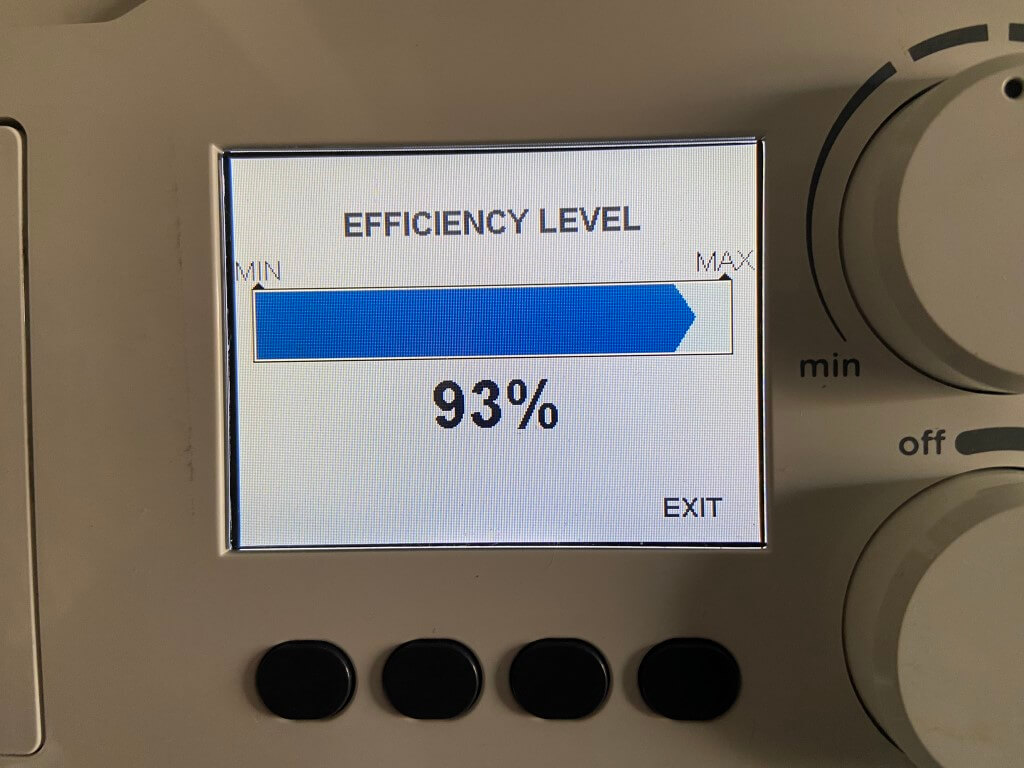
I have made some minor adjustments to my Hive schedule, implementing a 16oC Setback temperature rather than the 10oC previously used, the strategy behind this is using the house as a thermal store, and that is should use less gas overall raising the house temperature by a relatively small amount when demanded.
16 October 2023
The heating is on in earnest now as the temperatures are dropping, so I revisited the weather compensation slope information, necessitating a call to Ideal Technical to clarify slope settings.
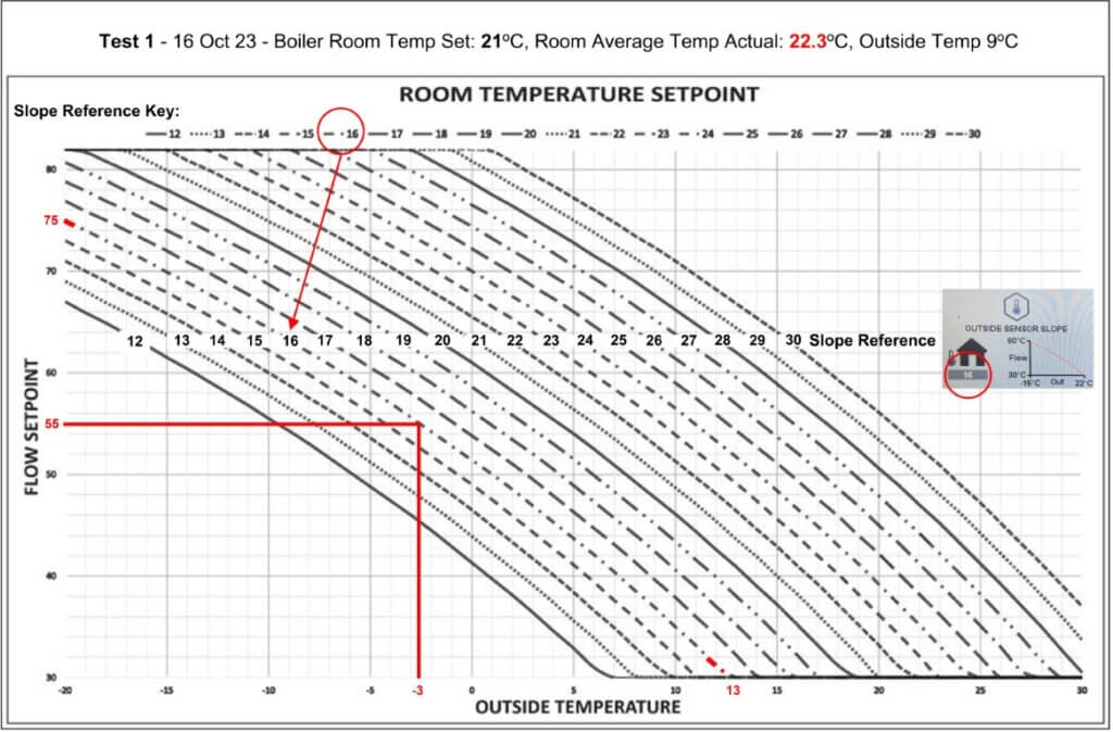
The graph above is within the documentation of the external weather compensation sensor and I was trying to figure out which slope to use with my system design of 55oC flow temperature when the outside temperature was -3oC.
I was overthinking it, simply the slope at which my setting intersect is the number that needs setting and I have modified the graph to make this easier for others to follow.
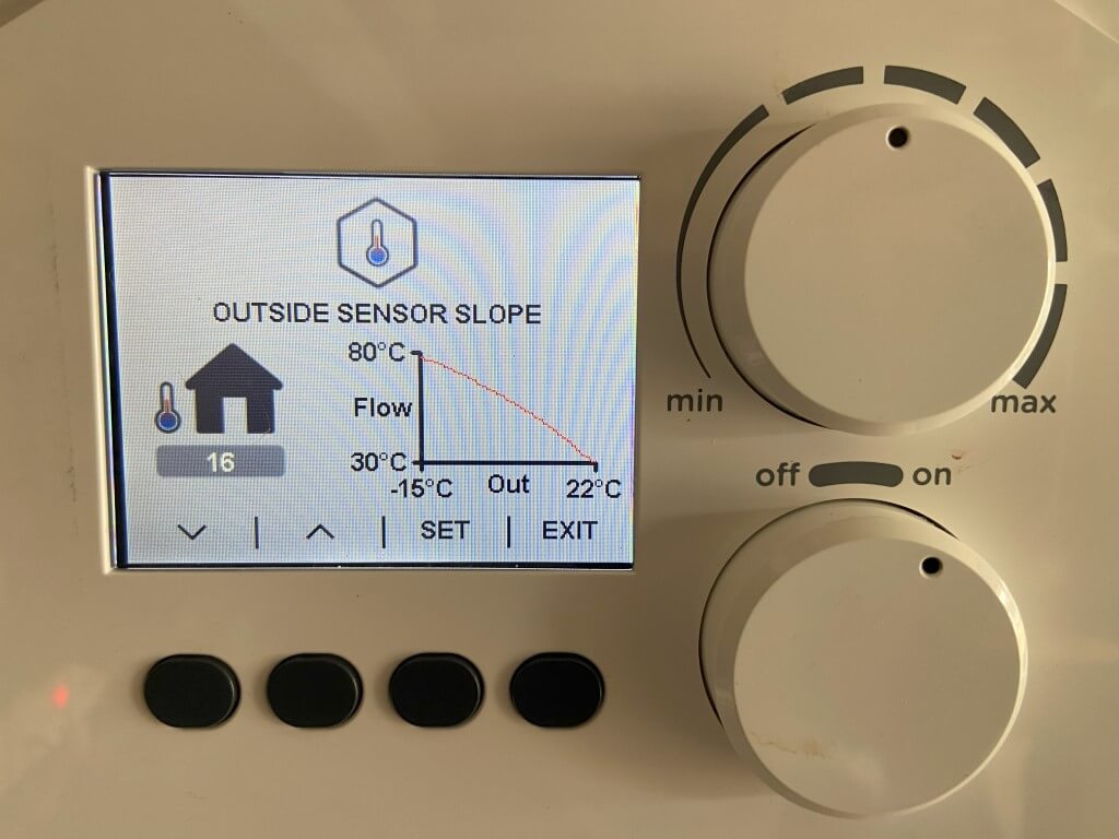
Slope 16 set, as the house no longer uses a thermostat, instead relying on the boilers weather compensated flow temperature to radiators to modulate according to the return temperature.
The flow temperature is based on a boilers room temperature setting which I have set at 21oC.
The key thing is that each rooms radiator is sized correctly to match its losses based on the heat loss calculation, if I have this wrong, then the room will either not reach temperature or be too hot.
Hive radiator TRVs have been set to 24oC as room overheat control and the Hall thermostat also is set to 24oC as protection.
Test 1 Result – With the settings above the average room temp went to over 22oC whilst upstairs, some of the TRVs which were set at 24oC, closed, the outside temperature was 9oC.
I will repeat this before adjusting further.
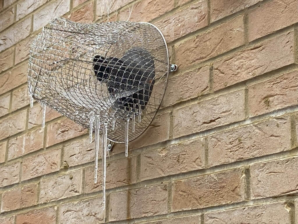
5 December 23, We have had below zero temperatures so this has been the ideal time to calibrate the weather compensation Slope curve and room temperature control.
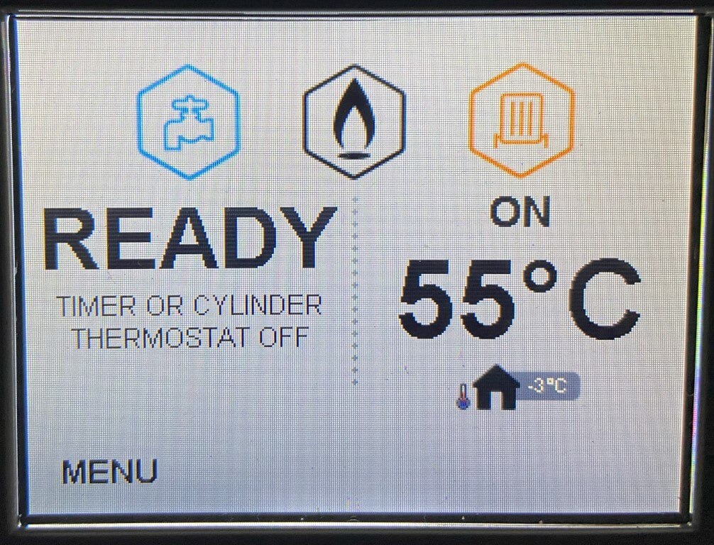
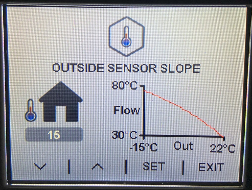
The above display is the designed boiler flow temperature at -3oC, the Slope curve was 15:
The room temperature control was set to 20oC:
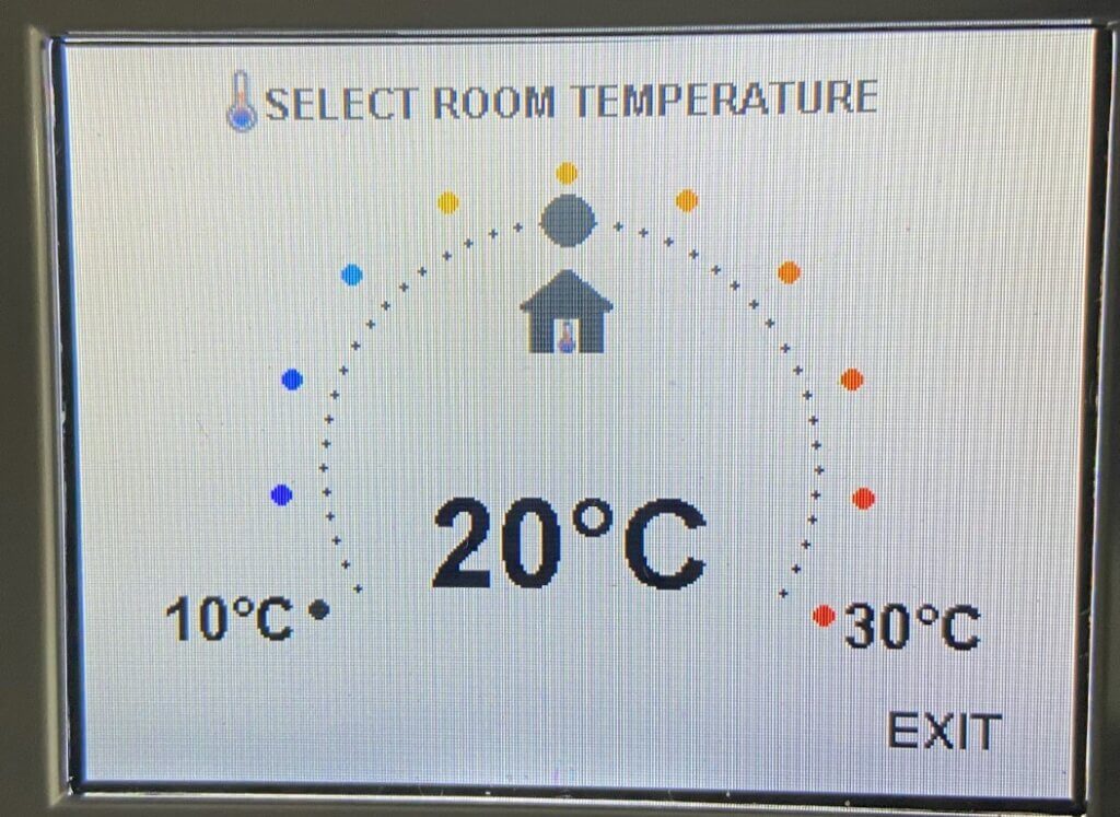
Ironically the displayed room temperature doesn’t mean that! What it means is a flow temperature adjustment band within the selected Slope curve, for example:
- Room Temperature Control 21oC =57oC flow temperature at -3oC
- Room Temperature Control 20oC =55oC flow temperature at -3oC
- Room Temperature Control 19oC =53oC flow temperature at -3oC
- Room Temperature Control 18oC =51oC flow temperature at -3oC
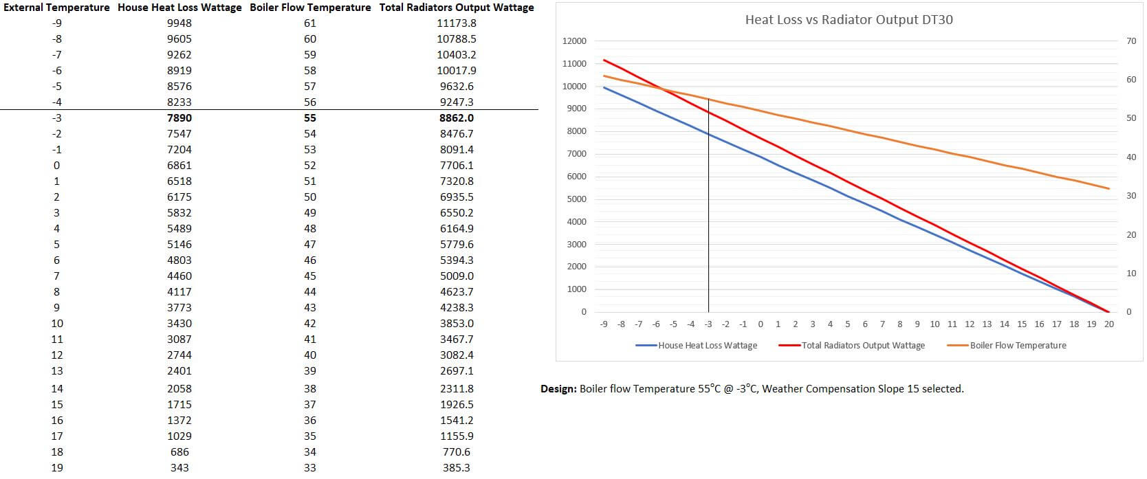
As stated earlier, my design flow is 55oC @ -3oC, the overall heat loss at -3oC is calculated at 7890 Watts/Hr, the total heat emitted by the radiators at 55oC is calculated at 8862 Watts/Hr.
My initial thoughts were ‘Open Loop’ control, i.e. letting the boilers flow temperature, based on the Slope Curve, balance house losses by adjusting the flow temperature, I’m having difficulty with this for two reasons;
The first is that the heat output of the radiators has to exceed house losses, otherwise it would never get warm 🙂 but this means that without any form of ‘internal temperature feedback, the house temperature overshoots and continues to rise,
The second issue is the Slope Curve, if I adjust the room temperature control flow temperature to closer match house losses when the house is at temperature, means that it will take ages to warm up.
The upshot of this is that I have reverted back to control using Hive and the ‘Heat on Demand’ (HOD) function which was the system I used before the boiler upgrade.
I have Hive TRVs on all radiators, the HOD function allows individual room temperature control, and rather than heat the whole house with ‘Open Loop’, enables me to have time and temperature based heating patterns based on the use of the room.
Still playing, so keep checking in.
21 January 2024
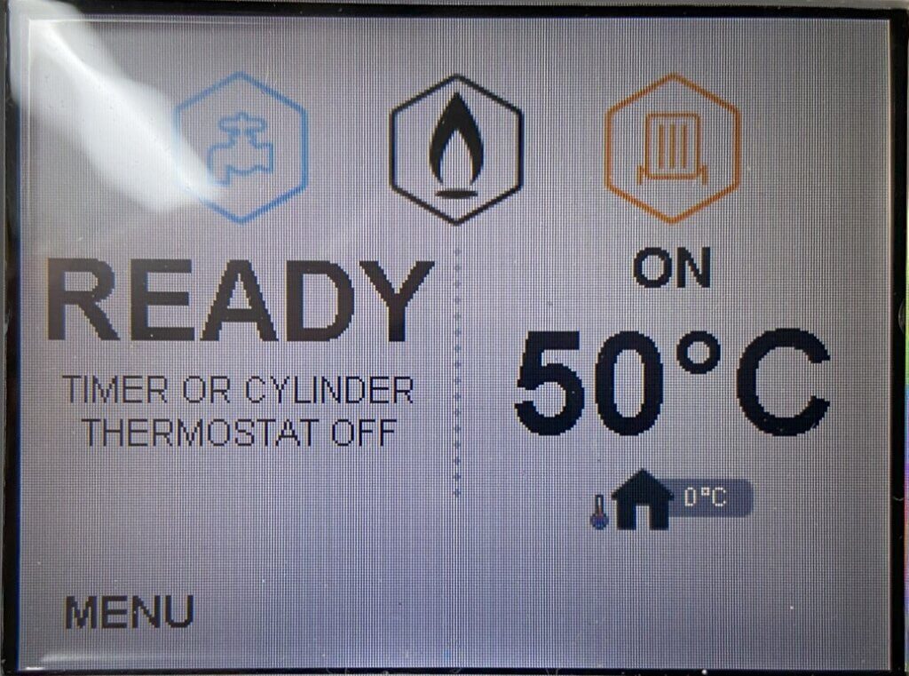
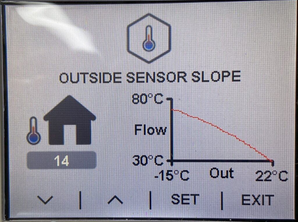
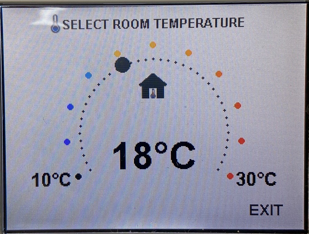
Yet more tweaking with the weather compensation slope and associated boiler room temperature control whilst the weather is still cold, the settings which seem to work well with increasing efficiency are a Slope of 13 and room temperature of 19oC:

Updates
4 May 23 – Boiler registration and Gas Safe certificate arrived from Ideal Heating.
6 May 23 – On going historic Gas kW usage graph in order to monitor the new boilers performance, new boiler installed part way through the period apr-apr 23.
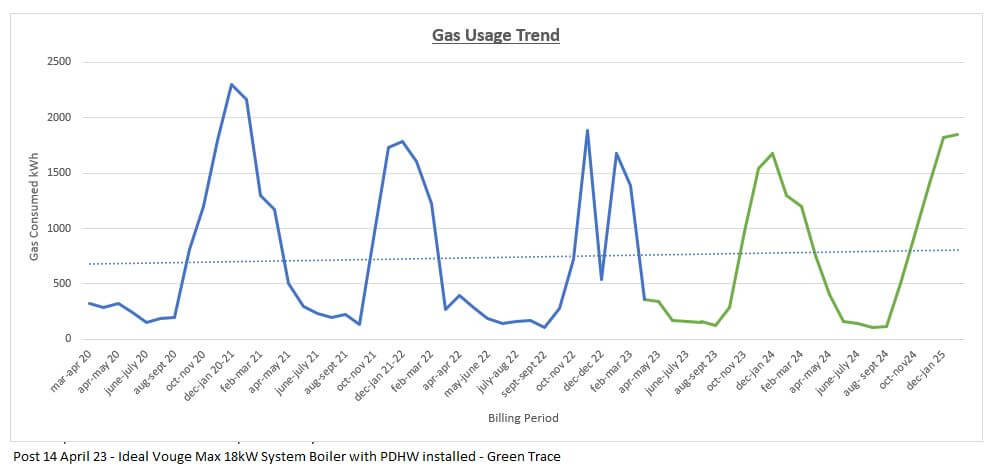
Note 1: – Gas consumption is due to heating water in the unvented cylinder, in September 23 Octopus Energy introduced periods of free electricity, therefore, hot water is heated by the immersion heater and not gas, hence the reduction in consumption for this.

