Category Archives: Ham Radio

Replacing Wire Rope in 12m MM0CUG Mast

Updated 29 September 2023

I had a senior moment when I tried to raise my electrically operated mast with the locking pin in, result that I snapped the wire rope !!
Well, what a nightmare and it was all of my doing.

The design of my mast is that it has a single electrically operated winch cable which can either lift the inner section of the mast, or luff the mast down for maintenance.

I had built a logic control for the winch, but didn’t engineer in being stupid, so when I decided to lift the mast after a number of years of not touching it, operating the momentary UP (raise) switch didn’t do anything, and not thinking I put the control into safety override mode to use the remote control winch hand control, pressing the ‘UP’ button, the winch motor started but sounded strained, which I put down to stiction of the mast, then ‘PING’ the cable snapped, it was at this point i realised that the inner mast pin was in place stopping it lifting.

So the predicament I have found myself in was that the mast can neither be raised or luffed down for repair, the only solution was the jack the mast up in-situ and replace the cable, not an easy task.

Equipment

The existing wire rope was 4mm diameter, so I took this as an opportunity to install 5mm, I bought 20m but used 19m, this was from GSProducts and cost including a wire clamp was £24.77.

The wire rope needed ferrules to crimp the end where it fits inside the inner box steel mast, so I needed these and a crimping tool, both of these were from The Wire Rope Shop costing £86.20.

The mast weights approximately 150Kg and will need lifting just under 600mm, I bought a Farm Jack from Amazon which cost £79.99.

Finally I needed a tower scaffold, I used a MiTower Plus from HSS (code 81216) costing £129.56 including delivery/collection for 7 day hire.

Not a cheap mistake!

How

First job was to fabricate a metal support which the mast was lifted on to:
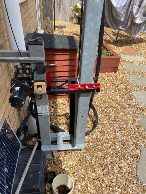
The idea behind this was that the masts pivot bolt would be removed enabling the whole mast to be lifted so that the hole in the mast which you can see in the picture, will be jacked above the black frame, where the red bracket will be clamped to the outer mast, and then lowered gently onto the frame to support the weight.
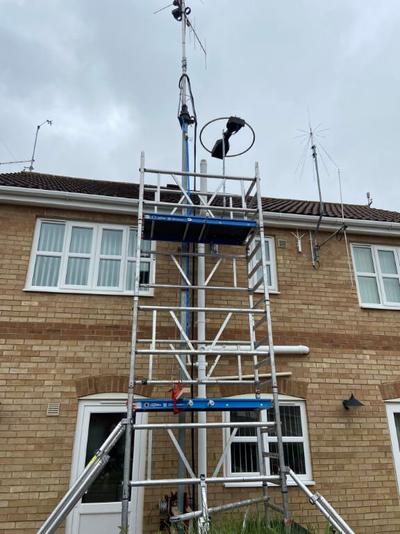
The scaffold went up easily enough to enable me to comfortably work on the mast, access was important as I needed the thread a replacement wire rope inside the mast, I also had to unbolt the top mast cage from the inner section steelwork, enabling the inner box section can be accessible at the bottom of the mast.
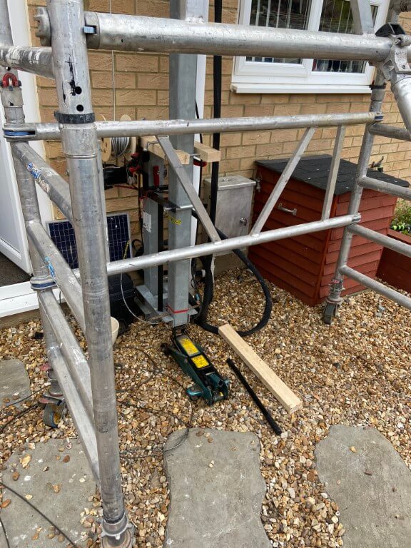
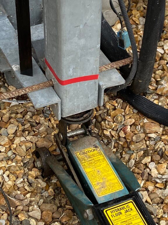
Using a car jack the masts pivot pin was removed and with a piece of steel rebar through the pivot hole, the mast rested until the next stage.

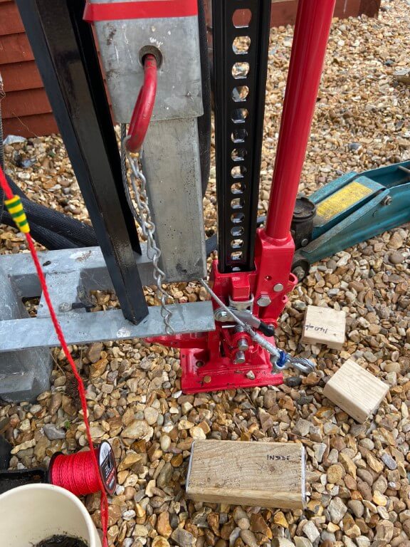
Using the Farm Jack to take the weight, the mast inched up to a height where a 260mm wooden block could be put inside the mast.

The mast was clamped and the Farm Jack was lowered, this was a mistake, the Jack simply slammed to the floor, fortunately the clamp held the masts weight and the block was inserted and we used a car jack for the rest of the lifting and lowering process but returned to the Farm Jack to lower for the main mast drop.

For future reference, the Farm Jack needs a downward force acting on it in order to lower in a controlled way, as we had removed the weight of the mast from the jack by clamping it, the Jack dropped.

With the mast supported, it was time for the next stage and that was to remove the bottom bolt from the mast top cage and begin the process of getting the cage box fixing to lower inside the mast.

This process was a bit tricky as it involved controlled lifting and lowing until all the bolts were removed and the cage assembly was sitting neatly inside the mast, unfortunately the inner mast was stuck inside the cage box.

A few lifts and rapid drops of the inner caused it to finally drop onto wooden blocks and we could get on with the repair.
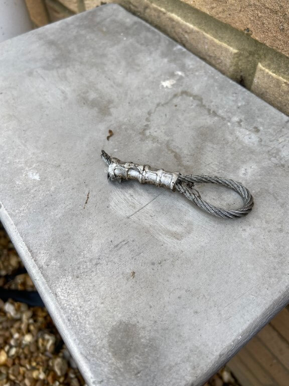
This picture shows the new steel wire rope with two crimped ferrules and a eye bolt, the rope is around a galvanized thimble, this was later modified to fit as in its current form, it was too big to go inside the 60mm x 60mm inner box section.
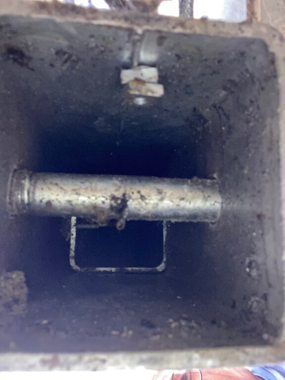
For clarity, the wire rope comes down the inside of the mast where it enters the inner mast through a hole 50mm up from the bottom of the mast, spacing of the inner section from the outer section is maintained by two sets of bolts further up the mast.

Reassembly

This was the most stressful part!

The inner mast section needed to be raised so that it sits inside the cage box, but no matter what we tried, the inner box could not be centralised and no way could the rotator assembly be manually lifted due to the weight and the fact that I would have needed a higher working platform.

My solution was to drill holes in the outer mast walls where the inner mast naturally was leaning, the holes were 9mm and I tapped them to accept grease nipples, hence they will server a purpose afterwards.

Once the holes were drilled, I used a couple of screwdrivers to manipulate the inner mast and on the second attempt, the inner slide perfectly into the cage, much to my relief as I didn’t have a plan ‘B’.

Finishing Off

All bolts back in and mast greased, I decided to replace the two mast limit switches and check the wiring, good job I did as one for the sensor wires had eroded through due to moisture ingress.

Glad its all back together and working now, but it was a lot of work and money for a lapse in concentration 🙁

Control Modification

In an attempt to stop and make me think, I’ve modified the control unit to include a key-switch with a warning notice attached to remind me not to be a dick!
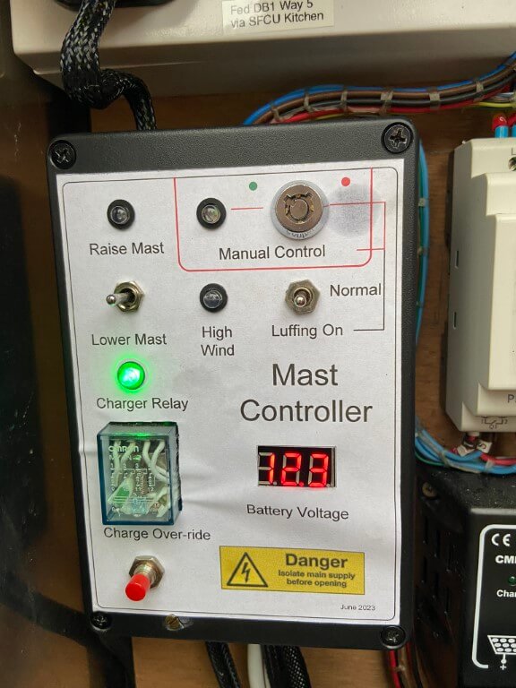
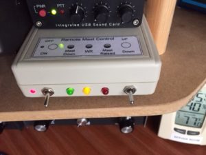
Mast controller now has a key-switch and warning RED flashing LED which illuminates if the control is set to either Luffing or Manual Control, the latter will only be enabled if the key is turned to the red dot.
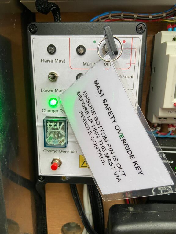
Hopefully these measures will work 🙂

Update

I added overcurrent detection to the winch motor as a belt and braces approach to avoid repeating my original mistake causing the winch rope to break when set to manual control.

My system uses a 12v car battery as the power source to the winch relay control and motor which is located in a battery box local to the mast.
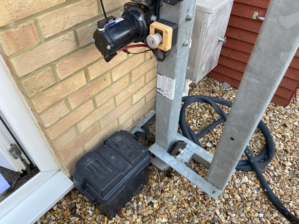
A 24v signal is sent to a relay in the battery box from the main controller and this in turn enables 12v to be sent to the motor controller for manual or wireless control, the project was to add a second layer to the relays control circuit.
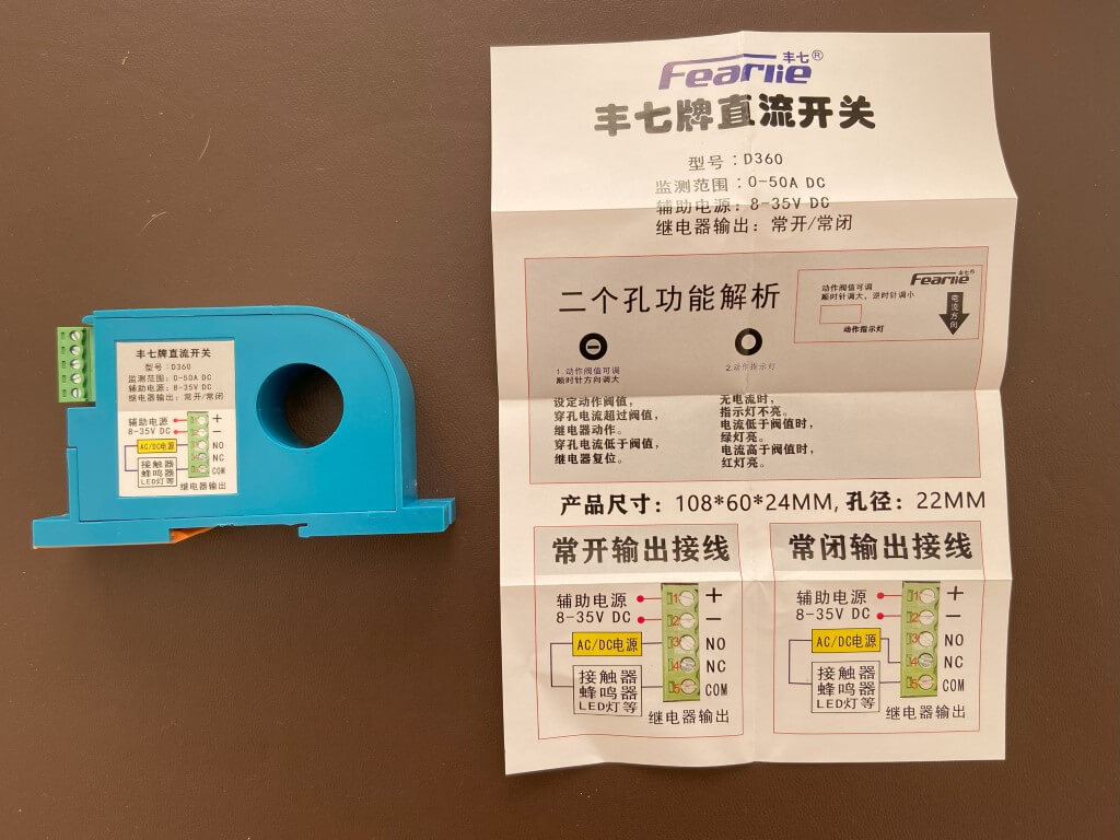
Using a clamp on ammeter I already knew the motors current draw when winching up, so I bought a 0-50A current relay from Aliexpress for £12.00.

With power applied and the battery positive cable passing through the current relay, I trimmed the potentiometer on the device so that it is just set below the tripping threshold.
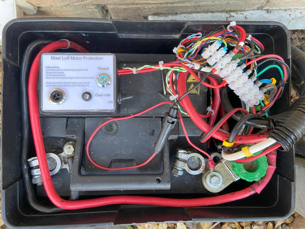
Bit of a messy picture showing the protection device in place with the blue led lit around the reset button indicating that the luffing relay is energised and the mast motor control is ready.
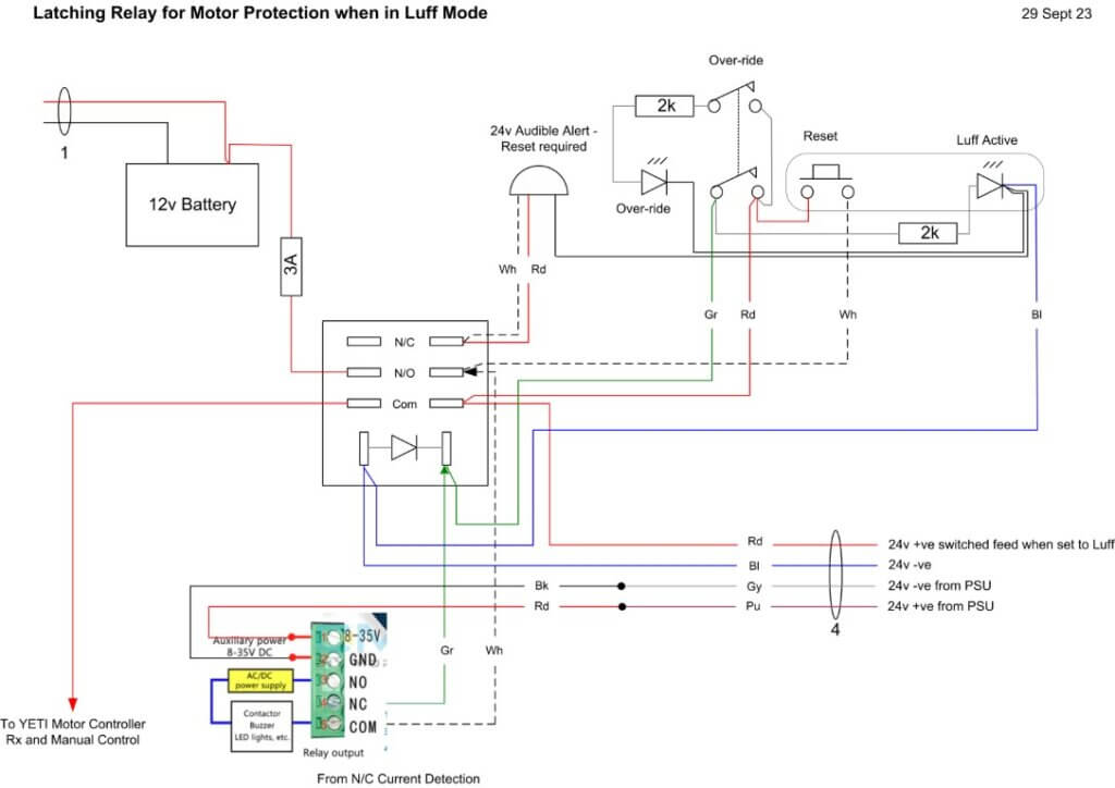
The circuit of the protection is straightforward, when the controller is set to Luff, a 24v signal is sent to a relay, the positive goes through the Normally Closed contacts on the current relay onto the Normally Open relay contacts of the motor controllers supply, therefore this relay will not latch until the relay contacts are shorted, in this case with the reset button.

When latched, the blue led will light and 12v applied to the motor controller, should any of the following listed things happen, the relay will drop out and remove power from the motor controller, stopping the motor until manually reset:

  • Luff signal removed by controller
  • Overcurrent relay contact open on detection of excessive current draw

In order to remind me to reset the protection relay when set to Luff, a buzzer will sound, this activates when the relay is not latched and is supplied by the Luff signal voltage from the main controller.
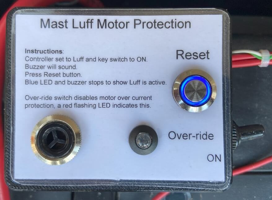
I did include a motor protection over-ride switch and flashing red led to show when it is on, this simple bypasses the current detection relay and will hopefully not be needed.

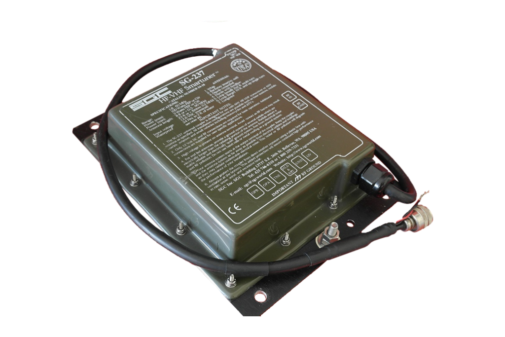
SGC Auto-Tuner SG-237 Repair

I have had the SG-237 for nearly 5 years and it has worked perfectly matching my random length wire across the bands, due to changes to the garden, I had to power down the SG-237 for a few weeks, on powering up, nothing would tune.

Checking current to the tuner showed that no power was being drawn, so off came the lid, and out came the voltmeter.

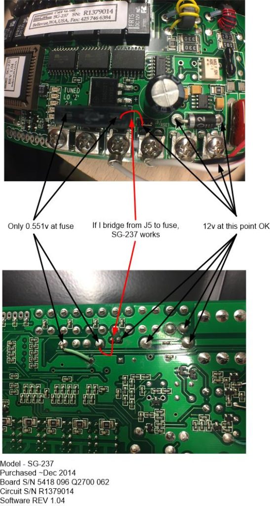
Tracing 12v through the circuit, it appeared their was a break between jumper J5 and the fuse holder, (the 2A fuse was in tact), but I couldn’t see any damage to the PCB tracks.

The reply from the SGC support ticket was within two days and their tech support said this was a very unusual fault and bridging from J5 to the base of the fuse holder was fine.

I can only deduce that the track link is made within one of the layers of the multi layer PCB, I did try and re float all the relevant solder connections, but this didn’t work unfortunately.

In the end, I soldered a link from the diode, bypassing J5 as I’ll never remove the link to the fuse holder, this link now removes another future point of failure and everything works just fine 🙂

Longwire supporting steel tube replacement with GRP

pole
New RED GRP tube delivered next day from Engineering Composites Ltd.

Link to previous blog on the longwire installation: HERE

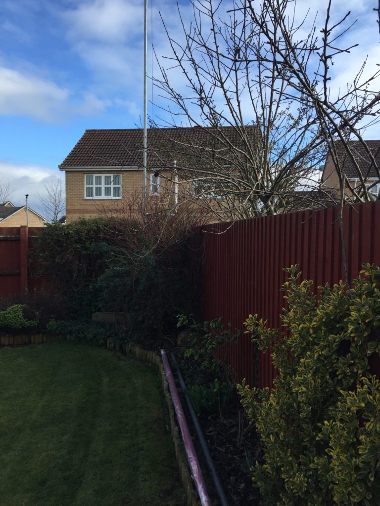
The existing steel tube is outside of my physical strength to bring down from the vertical and put back up again, I was very reliant on a local scaffolder to do this for me, for which I was ever grateful.

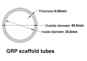
My intention has always been to replace the galvanised steel 6m scaffold tube supporting my longwire with a lightweight Glass Reinforced Plastic (GRP) composite version, the two main reasons are maintainability and performance.

Performance is related to the effect on the antennas radiation pattern by the influence of the steel tube, use of a non conducting supporting tube will remove this effect.

The 6m tube in RED was bought from Engineered Composites Ltd of Chester, the total cost including VAT and UK Delivery was £130.54.

Product Code TU627IR

The GRP scaffold tube is only available from Engineering Composites in 6m lengths and in either Red or Yellow, I choose red as it was going to painted light grey anyway and red is way cooler than yellow, didn’t want the neighbours to think I’d installed a Gas vent pipe :-).

red pole

I used Ultra Grip Primer before applying the top coat, and it seems ok, time will tell how effective it has been.

pole up

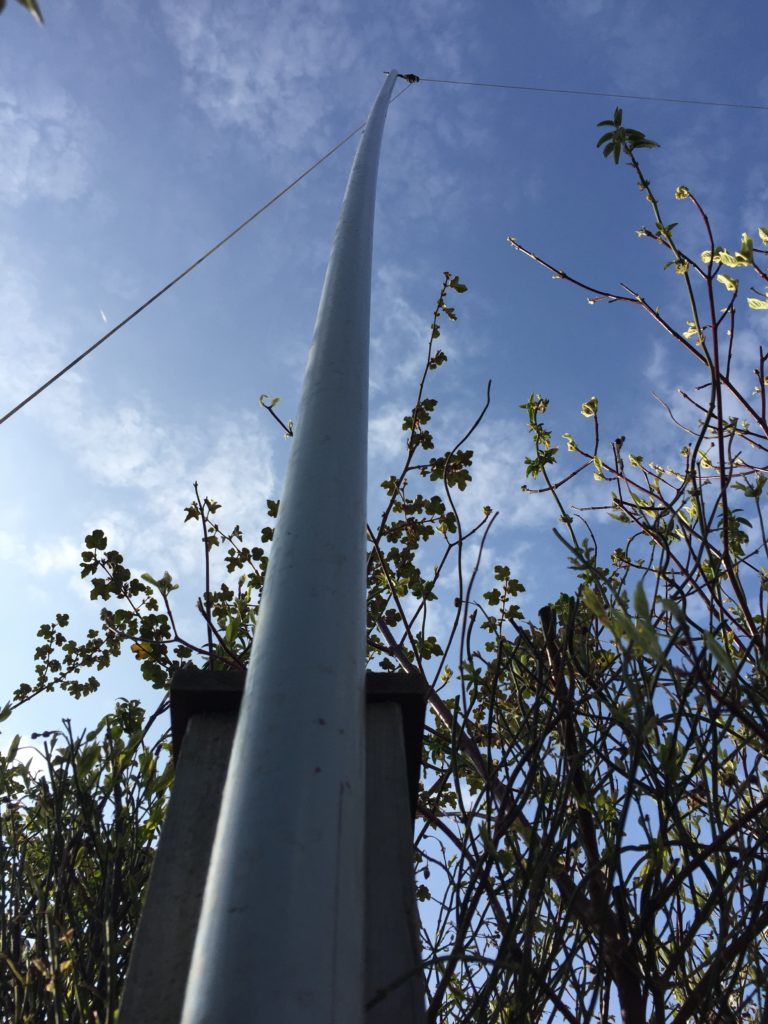
GRP tube installed without any assistance as its 75% lighter than its steel equivalent, I noticed that the tube has a greater deflection that the steel version which is only to be expected, the highest wind the steel tube had to cope with was a gust of 62mph, so it will be interesting to see how this copes with wind!

MFJ 1786 Magnetic Loop Modification

mfj

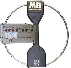
I bought at used MFJ 1786X (240v version) from Tony G3RGQ (sadly now SK), I have been after a magnetic loop for quite a while, so when the opportunity presented itself to buy one at a reasonable price, I went for it.

The 1786 covers from 30m through to 10m, looking on Youtube was a modification to increase coverage into the 40m band.

After looking at the video it was off to eBay:

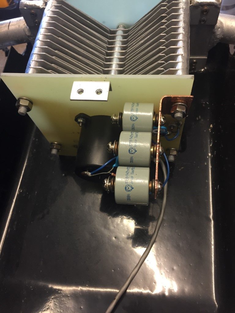
  • K15U-1 47pF 10kV 8kvar Capacitors including delivery from Ukraine £13.57.
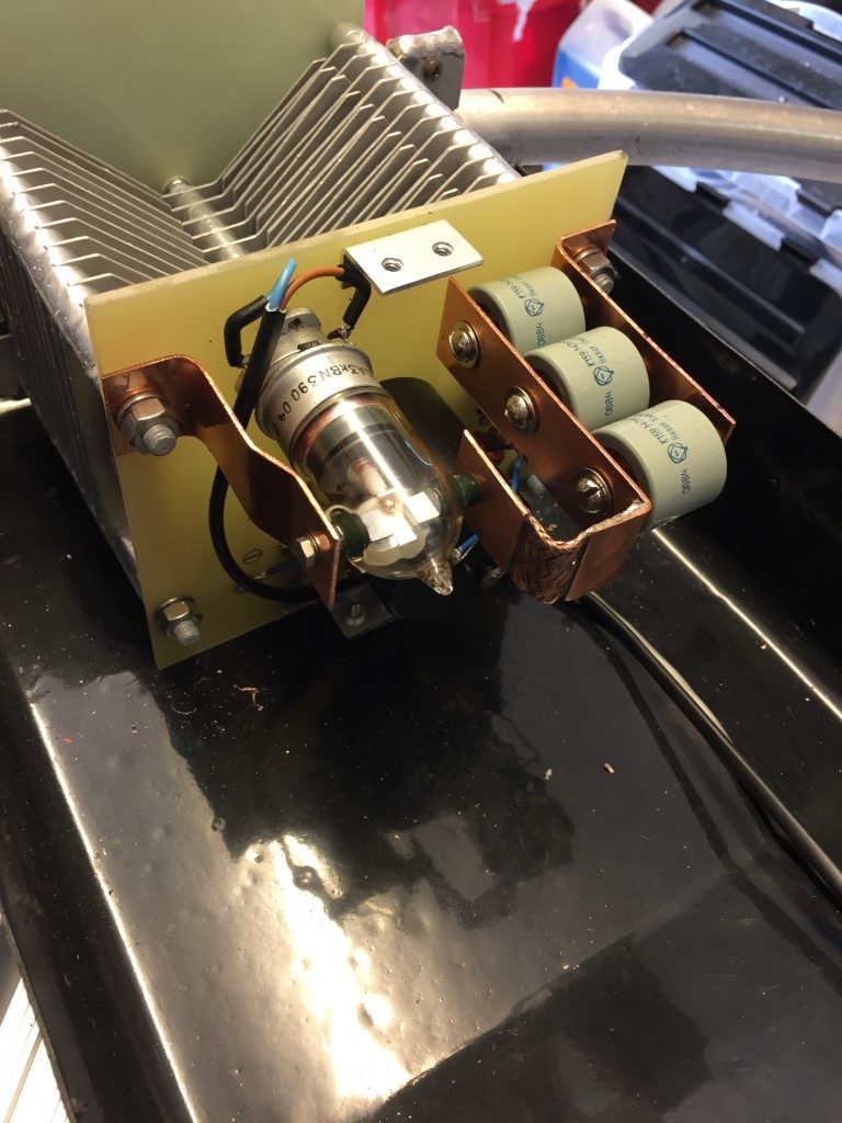
  • Vacuum Relay 10kV 3A including delivery from Poland £23.53.

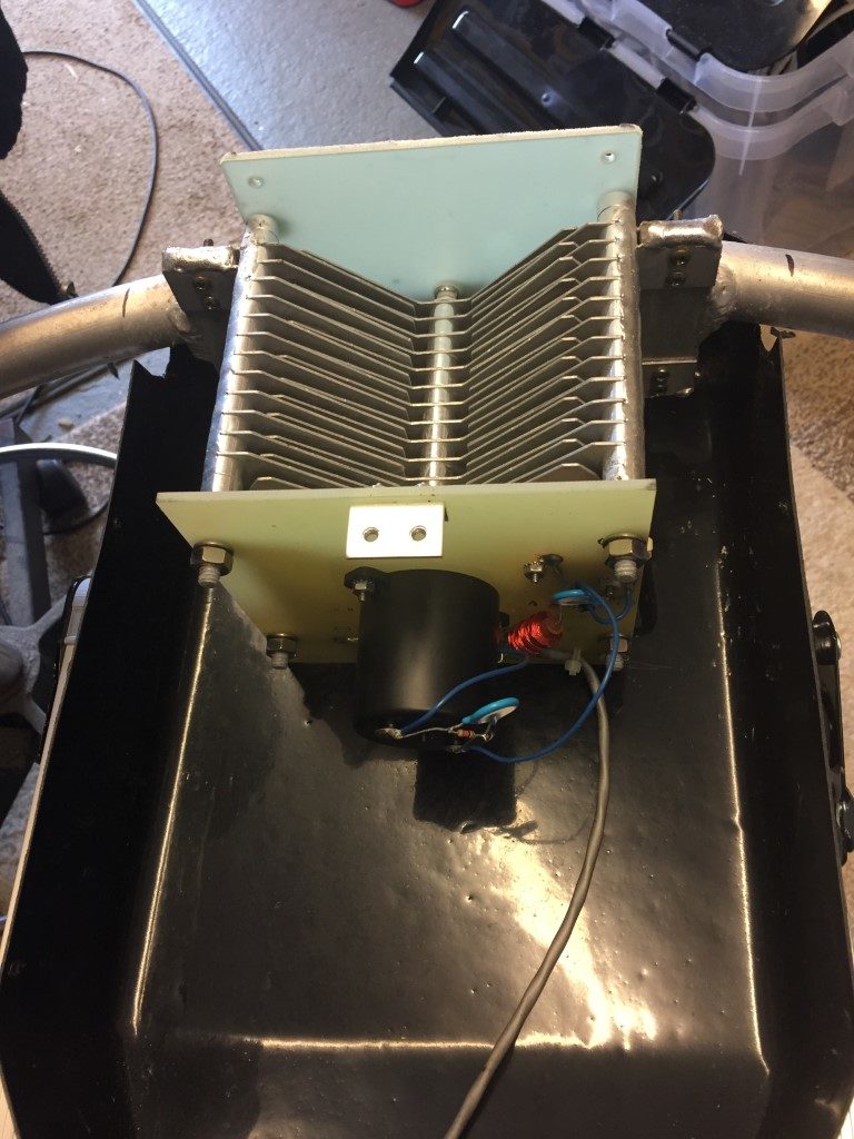
Opening the case and looking at the butterfly capacitor, I located a way to securely mount the capacitors and relay.

butterfly

I had some left over copper sheet, so I cut a 25mm wide strip 100mm long and used this as the capacitor linking strap and mounting brackets, making sure I had a solid connection to one side off the butterfly capacitor.

caps

The relay was mounted to the opposite side of the butterfly capacitor using a similar strap to that on the capacitors. To avoid straining the glass relay switch connection, I used some RG213 braid to link the capacitors connection to the relay, I deliberately didn’t secure the base of the relay to the fibreglass insulating sheet, this is to make the relay ‘floating’ in an attempt to reduce the chances of relay breakage.

relay

I installed a ‘flywheel’ diode across the relay coil (coil voltage  27VDC) to protect the operating switch in the shack.

Once the loop case was refitted, the modification was tested and works fine, many thanks to the Youtube author for sharing his practical experience.

Update 1 June 18

I bought a offset pole and 9 x 9 bracket to mount the magloop on, the existing 6 x 6 bracket was too undersized and slightly in the wrong position, the new bracket was fixed with M10 sheild anchor rawlbolts.

The tricky bit was getting it mounted due to it being top heavy compounded by a cranked pole, the solution was to use a pully arrangment from the mast to take the weight to help get me up the ladder and also position the pole to put the ‘U’ bolts in 🙂

loop up

Sonoff 4Ch Pro WiFi/Internet Switch Linked to Alexa

Sonoff 4 Channel Pro

sonoff

I have had an Amazon Dot for a while and use the interactive plugs and lights all the time, one of the plugs is for my Ham Radio PSU, so I have been looking for a relay interface which will work with the Amazon Dot, one of the key requirements is that the relays must be able to pulse on then off.

The Sonoff 4Ch Pro costs ~£25 and has 4 programmable relays including the ability to ‘inch’ a relay (pulse on then off), the reason this is important for me,  is that it allows a momentary trigger to the PLC controlling my automated mast.

The Sonoff 4Ch Pro is well made and can be powered from either the mains or 5 – 24v DC, relays are all voltage free.

The Sonoff App is EWeLink and allows direct control of the relays from anywhere, this App is then linked to the Amazon Alex App to allow voice control of the relays,m if you want to use voice control from your smartphone, Reverb is good.

EWeLink App needs an account setting up, once this is done, follow the instructions to pair with your router.  The default pairing LED flashing sequence did not work for me, I had to keep my finger on a relay button until the blue LED rapidly flashed and then followed the instructions.

Once paired, the blue LED remains steady, after a power down, WiFi locks within 20 seconds.

Sonoff Enclosure

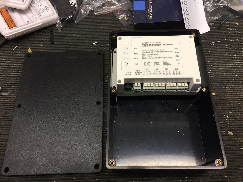
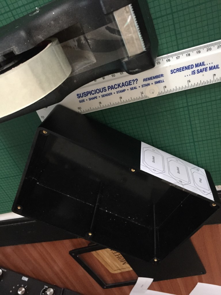
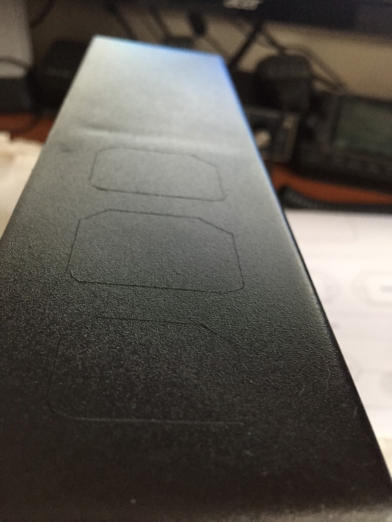
I decided to mount the Sonoff 4Ch Pro in a 220 x 150 x 96mm ABS enclosure (£9.70 eBay), in Visio I drew the cutting stencil and transferred this to the enclosure.

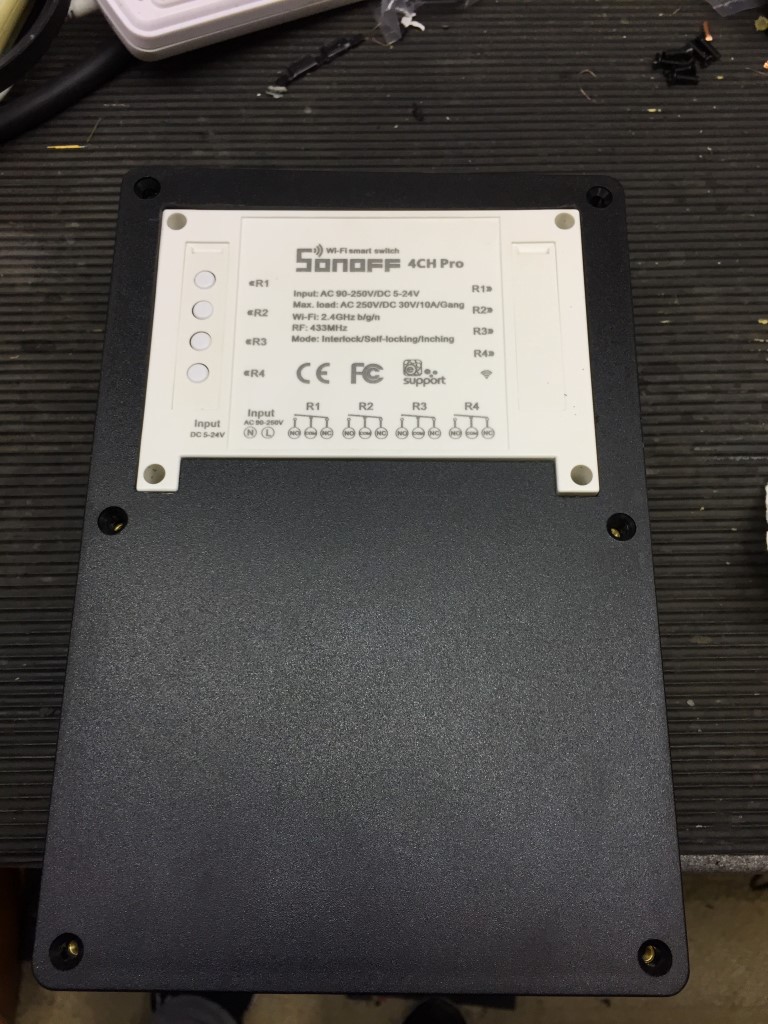
The width of the Sonoff needing trimming slightly to make a snug fit, the get the correct height I packed the unit with 25 x 25mm wood off-cut.

enclosure

Using a Dremel equivalent, the lid was cut to accept the Sonoff.

enclosure

The IEC plug and socket stencil was attached to the side of the enclosure, using a scalpel, the cutting pattern was transferred.

cut

cut

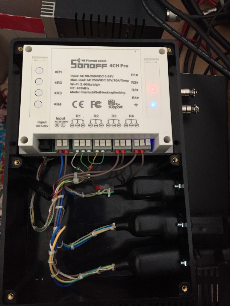
Wired Sonoff 4Ch Pro, Relays 1 & 2 momentarily switch +24v as a trigger input to either Raise or Lower my mast, Relays 3 & 4 latch to supply individual IEC outlets.

The Relays and outlets are rated at 10A, the feeding plugtop has the appropriate fuse fitted.

wired

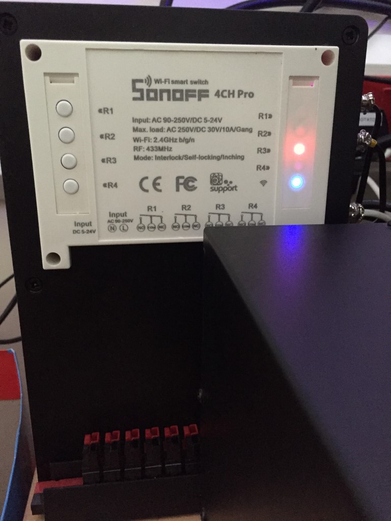
Finished unit tucked behind a PSU, LEDs show that Relay 3 is energized and WiFi is connected.

finished

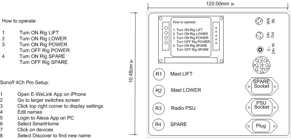
The label below is the remind instructions on the voice commands (prefixed with ‘Alexa’) and how to change the relay names.

operating instructions

Update –

Had a huge headache trying to get this unit to re-pair once I had done some modifications to my home network and access point, looking through the help forums a large number of others are having the same problem, the solution which worked for was to put the iPhone in ‘Airplane Mode’ and follow the process to pair an Android phone (Touch) and not AP which had worked previously. What didn’t help was an unannounced outage of the European Sonoff servers!

The second issue which came to light was relay 4 would randomly operate, the fix was very simple, press and hold the internal S5 button to erase any pre-enabled RF switches.

Mast and Wire Rope protection & lubrication system

Mast and Wire Rope protection & lubrication system

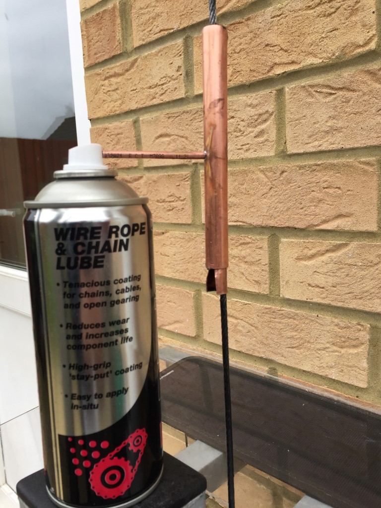
I wanted a quick and easy way of applying protective lubricant to the wire rope which raises and lowers my mast, my first effort involved a paint brush and a tin of grease and I thought then that their must be a better method, both in terms of speed and effective application.

The option I chose was to use a spray wire rope and chain lube in conjuction with a home brew applicator.

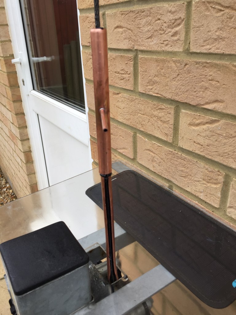
applicator

The FORCE spray lube costs £6.25 for 400ml from eBay, the details of product are:

  • A long lasting highly tenacious spray grease which reduces wear and increases chain life.
  • High grip, anti fling properties provide long lasting, high depth lubrication and protection.
  • Penetrates inner rollers and resists the highest shock loads.
  • Ideal for chains, cables, wire ropes, fork lift chains, open gears and tail lift assemblies.
  • Reistant to weather and salt, provides high resistance to wash off.
  • ‘O’ Ring Safe unlike other greases!

Parts

  1. 1 off 10mm copper pipe 150mm in length
  2. 1 off 15mm copper pipe 135mm in length
  3. 1 off 4mm copper pipe 60mm in length
  4. 1 off 12mm panel grommet

Construction

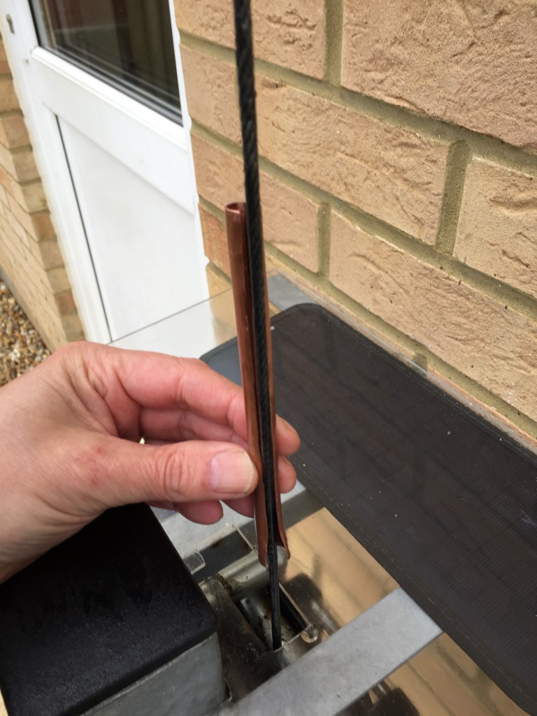
The 10mm pipe had a 5mm slot cut down the complete length to allow the pipe to fit over the wire rope, at the base of the 10mm pipe I ‘flared’ this to 14mm.

The 15mm pipe was cut at one end with a roller type pipe cutter (pipe slice) and this formed a nice curved lip, at the other end I used a hacksaw, this pipe also had a 5mm slot cut down its length, for the cutting of the slots I used a dremel with a mini abrasive disc.

As the spray gease doesn’t come with extension tubes, I decided to use 4mm copper pipe (the 2mm inside pipe bore is perfect to slide over the spray cap nozzle), this was soldered half way up the 15mm pipe, this pipe enters directly opposite the cut slot. To act as a ‘key-way’ it protudes into the pipe by 1mm.

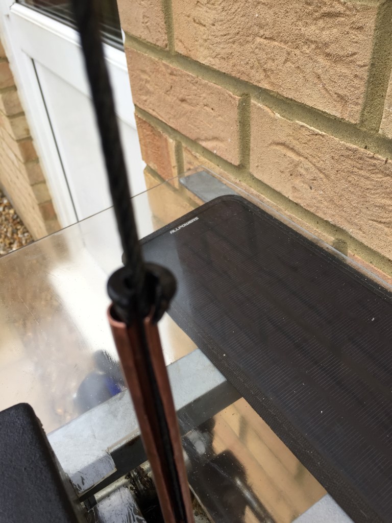
A 12mm panel grommet is cut to fit inside the 10mm pipe.

Operation

The 10mm pipe is slid over the cable with the flared section at the bottom:

10mm pipe

The grommet is installed at the top:

cut grommet ready to fit in pipe

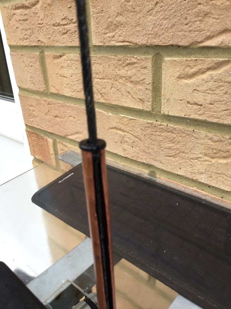
grommet in 10mm pipe

The 15mm pipe is now slid over the cable above the 10mm pipe and rotated so the grease inlet is inline with the slot in the 10mm pipe:

4mm inletNoting the alignment, the 10mm pipe is pushed inside the 15mm pipe, the 4mm pipe protuding inside the 15mm pipe ensures the 10mm pipe can only fully slide in if the slot aligns, The lip on the 15mm pipe holds the grommet in place:
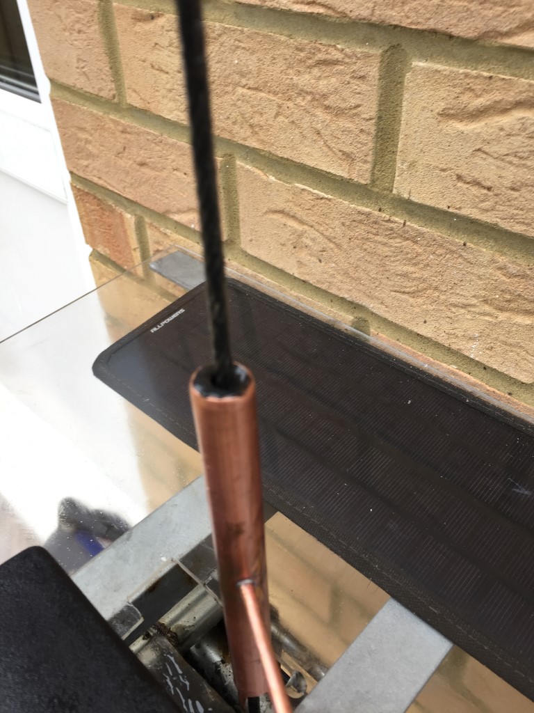
grommetThe finished product works quite well and gives an even coating to the wire rope, the length of the 4mm pipe was to allow the spray can to rest on a bracket, so I simply raise the mast and hold the spray button down 🙂
applicator

Mast Lubrication

For the mast lubrication I use Lithium Grease, this is easy to apply from the spray can and is designed for metal to metal contact, a typical lubrication application for my mast with a rising section of 5.4m is 200ml.

The Hazard Data sheet for WD40LG White Lithium Grease.

Radio Mast Automation – Part 5: Control Modification

Updated 29 September 2023

Since my last blog on Mast Automation when I thought I’d finished the project, I have made some changes to my weather station which means I no longer have an output to the mast controller, this output used to trigger the mast to lower when the wind speed hits 30 mph.

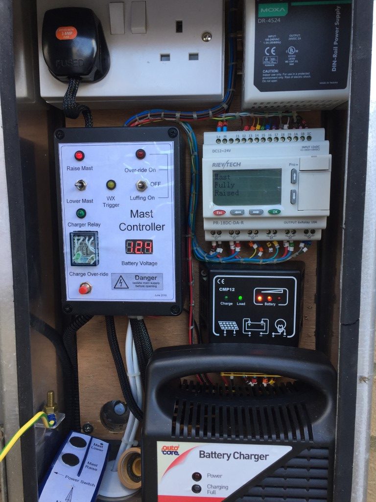
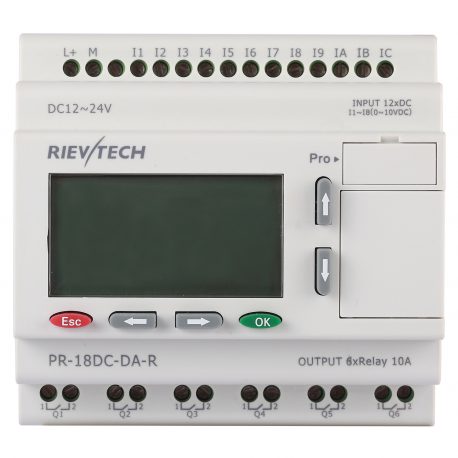
I decided to update the discontinued version of my Programmable Logic Controller (PLC) with a Rievtech PR-18DC-DA-R from Audon Ltd, this unit is a direct replacement for my old PLC and has 12 Inputs and 6 relay Outputs.

Rievtech PLC

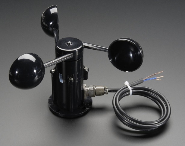
The PLC accepts a number of input types, in my application I’m simply switching a voltage state with the exception of one of the inputs which is configured as an Analogue input, to which I have connected my mast mounted Anemometer (https://www.mouser.co.uk/ProductDetail/485-1733?R=1733virtualkey54950000virtualkey485-1733) as a means to trigger mast lowering during unsafe wind conditions.

1733

Adafruit 1733

TECHNICAL DETAILS

Dimensions:

  • Height (base to center): 105mm / 4.1″
  • Center out to Cup: 102mm / 4″
  • Arm Length: 70mm / 2.8″
  • Weight: 111.8g

Wire Dimensions:

  • Wire Length: 99cm / 39″
  • Plug Length: 30mm / 1.2″
  • Diameter (thickness): 4.8mm / 0.2″

Specifications

  • Output: 0.4V to 2V
  • Testing Range: 0.5m/s to 50m/s (111.8 mph)
  • Start wind speed: 0.2 m/s
  • Resolution: 0.1m/s
  • Accuracy: Worst case 1 meter/s
  • Max Wind Speed: 70m/s (156.5 mph)
  • Connector details: Pin 1 – Power (brown wire), Pin 2 – Ground (black wire), Pin 3 – Signal (blue wire), Pin 4 not connected

I tested the output  with help from my better half by driving at steady speed and monitoring the output from the anemometer:

  • 0 mph = 0.40  mV
  • 25 mph = 0.75 – 79 mV
  • 30 mph = 80 mV
  • 31 mph = 81 – 88 mV
Anemometer
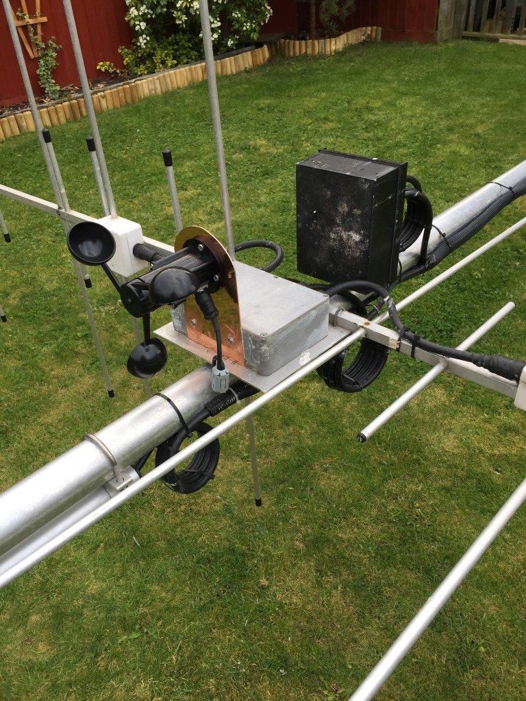
Anemometer mounted on 2m/70cm H/V relay switch box

I mounted the anemometer to the top of my mast to get a representative wind speed, the next job was to strip out the old PLC from the control cabinet.

Mods
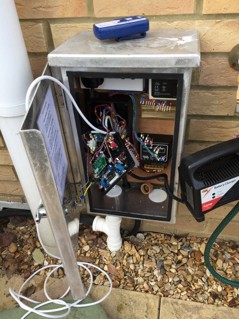
Starting mods, (hand held winch controller on top of cabinet)

I needed to make several changes from the original design in order to free up one of the PLC’s inputs, also out of the 16 Inputs only the first 6 allow analogue inputs, so some moving of inputs was needed along with some minor works to the LED voltages and override/luffing switch.

PLC
Completed Cabinet

All went back together quite nicely but an intermittent problem remained after the PLC replacement in that when the mast completed the mast raise cycle, the motor would immediately reverse and the mast would lower.

Hooking up the laptop to to the PLC, I selected ‘live monitoring’, this displayed the input and output condition, this showed that after operating the ‘raise’ toggle switch (centre bias On – Off – On centre off), the ‘lower’ switch input also went and remained high. This output to the PLC caused the motor to immediately  change direction and lower the moment the mast raised sensor was triggered.

To reduce the chance of a repeat problem occurring, I modified the replacement DPDT switch wiring so that both poles need to switch in order for a signal to pass.

switch wiring

Prior to starting the upgrade works I had the programmed PLC on the bench and I thoroughly tested all control permutations by simulation using the software from Audon Ltd to ensure correct operation.

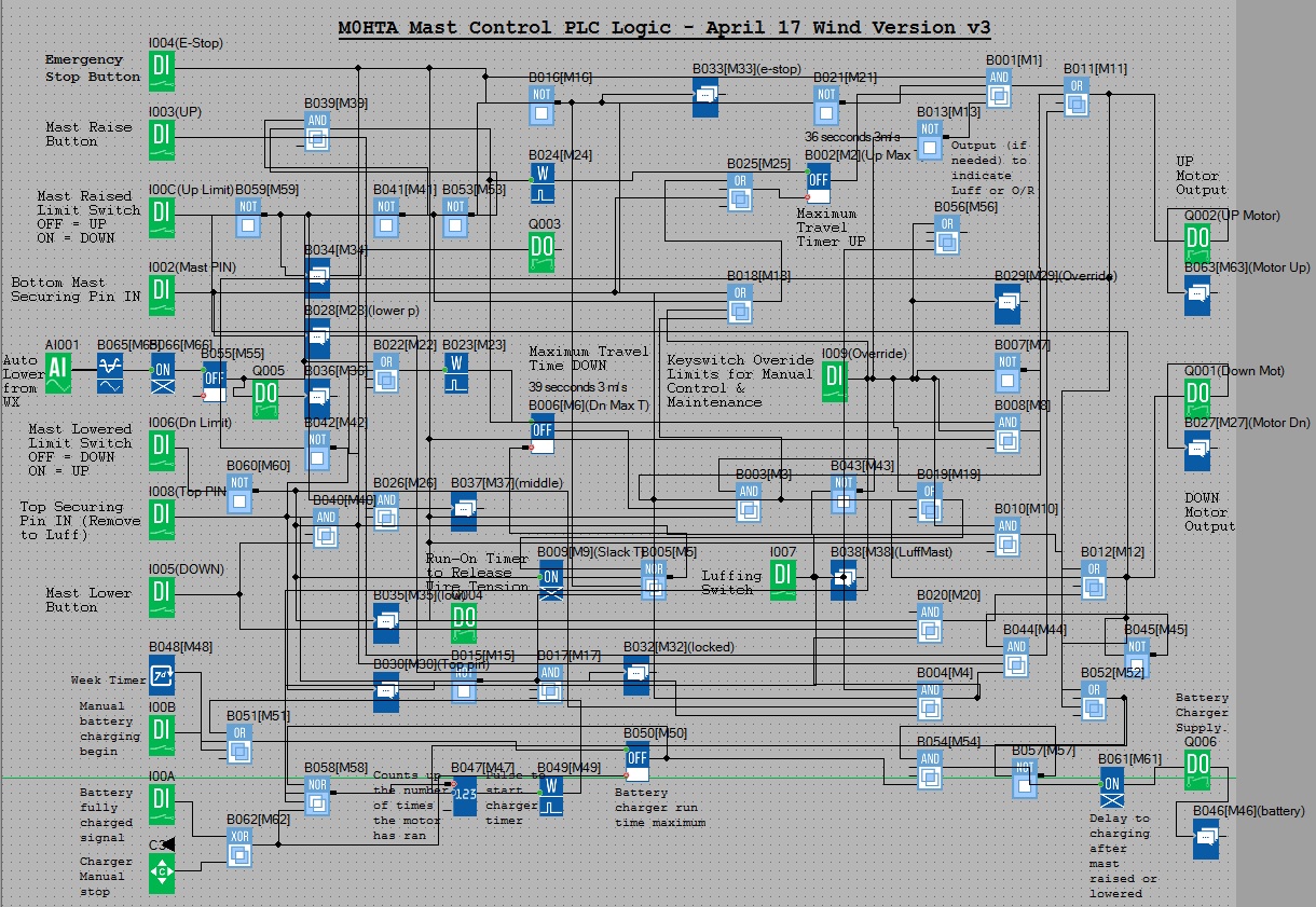
v3
PLC Modified block diagram (Program File for use with xLogicsoft)

As you can see, the logic has grown with the project, I’m sure this could be significantly simplified, however, it works for me.

Mast Control Logic

Pressing the Emergency Stop button will inhibit any operation and reset any timers which are running, also a message is displayed ‘*warning* E-STOP operated’

Raising the Mast

Conditions –

  • E Stop not pressed. (Input 1004).
  • Top Securing mast pin IN. (Input 1008).
  • Mast in the lowered position. (Input 1006).

Trigger –          Switch input momentary high. (Input 1003).

Action –

  • Lower switch inhibited.
  • Switch input via wiping relay with a 1 second ON timer to ensure momentary trigger to the next stage.
  • 36 second up timer start to operate Up relay (fail mechanism in case the ‘raised’ sensor fails).
  • Up relay closes to energize motor drive. (Q002).
  • After expiry of Up timer or on activation of the Up sensor, Up relay opens.
  • Mast raised output relay energizes. (Q003).
  • Message displayed ‘up motor running’ then ‘mast fully raised’.

Lowering the Mast

Conditions –

  • E Stop not pressed. (Input 1004).
  • Top Securing mast pin IN. (Input 1008).
  • Mast in the raised position. (Input 100C).

Trigger –          Switch input momentary high. (Input 1005).

Action –

  • Raise switch inhibited.
  •  Switch input via wiping relay with a 1 second ON timer to ensure momentary trigger to the next stage.
  • 39 second down timer starts to operate Down relay (fail mechanism in case the ‘lowered’ sensor fails).
  • Down relay closes to energize motor drive. (Q001).
  • After expiry of Down timer or on activation of the Down sensor, run on timer operates for 0.15 seconds to take slack off winch cable.
  •  After expiry of run-on timer, Down relay opens.
  • Mast lowered output relay energizes. (Q004).
  • Message displayed ‘down motor running’ then ‘mast fully lowered’.

Wind Speed Triggered Auto Lower

Conditions –

  • E Stop not pressed. (Input 1004).
  • Top Securing mast pin IN. (Input 1008).
  • Mast in the raised position. (Input 100C).

Trigger –           Wind measured via Anemometer at 28 mph for 15 seconds. (Input A1001).

Action –

  • 0.4 – 2v Anemometer to Analogue Threshold Trigger output set go high at 80 mV and off at 76mV, these values equate to ~28 mph and ~24 mph respectively.
  •  ‘On Delay’ timer from analogue threshold trigger set for a sustained output of 15 seconds duration before the next stage is enabled in order to reject gusts.
  •  ‘Off Delay’ timer set to 10 minutes, if no input from the ‘On Delay’,  ‘Off Delay’ resets.
  • Whilst the ‘Off Delay’ timer is running, the WX Amber LED is lit. (Q005).
  • Output from ‘Off Delay’ to wiping relay timer set to 1 second to ensure a momentary output to the next stage.
  • 39 second down timer starts to operate Down relay (fail mechanism in case ‘lowered’ sensor fails).
  • Down relay closes to energize motor drive. (Q001).
  • After expiry of Down timer or on activation of the Down sensor, run on timer operates for 0.15 seconds to take slack off winch cable.
  •  After expiry of run-on timer, Down relay opens.
  • Mast lowered output relay energizes. (Q004).
  • Message displayed ‘high wind trigger auto-lower active’.
Amber LED indicating high wind has triggered lowering the mast and inhibiting it from raising whilst lit.

Battery Charging Process

The winch has 3000lb capacity from Winch-It and is powered by a 12v car battery with a capacity of 45Ah – 360cca.

Normal Operation –    25w solar panel connected to the battery via CMP Solar Charge Controller.

Automatic Operation –

Trigger –       After 4 operations of the motors (raise & lower twice) or Weekly – Sunday 01.00.

Action –

  • Multi-pole relay energizes after a 2 second delay via Q006, this:
  • Disconnects the solar panel.
  • Applies mains to a 4A output battery charger (charger sized for Ah of battery).
  • Connects the battery charger output to the battery.
  • Message displayed ‘battery charging’.

Charging ceases when:

  • Battery terminal voltage reaches 14.14v (Over-voltage detection module to Input 100A).
  • 8-hour battery run timer expires.

Manual Operation –

Charging Start – Push button in control cabinet (Input 100B).

Charging Stop – Cursor key on PLC (C3).

Notes-

  1. If the battery charging cycle has started and the motor (either up or down) is operated, charging will cease and resume after a delay of 2 seconds after the motor has stopped.
  2. Up-Counter resets to zero when the charger is ON.

Luffing the Mast

Conditions –

  • E Stop not pressed. (Input 1004).
  • Top Securing mast pin Out. (Input 1008).
  • Bottom Securing mast pin In (Input 1002).
  • Mast in the lowered position. (Input 1006).
  • Luffing switch set to On (Input 1007).

Trigger –           Momentary switch (raise or lower) (Inputs 1003 or 1005).

Action –            Operating the Luffing switch supplies power to the wireless receiver and manual switch which came with the Winch-It kit via a relay , the supply for this is taken from the Luffing/Override indicator LED, (the Luffing switch is a Double Pole Double Throw On – Off – On, the LED is fed from one side of the switch).

A further change to the control is to from latching to momentary switch operation allowing the motor to be ‘inched’ via the wireless handset or panel switches in the control cabinet.

Using the handset allows the mast to be walked down whilst lowering or the reverse when reinstating the mast to the vertical.

Message displayed ‘mast switched to luff’.

Override

Operating the Override switch bypass all limit switches and enables momentary manual control.

Message displayed ‘ override switch on’.

Other Alert/Warning Messages

Top pin in, message displayed ‘top mast securing pin in’.

Bottom pin in, displayed message ‘bottom securing pin in’.

Both top and bottom pins in, message displayed ‘both mast securing pins in’.

Update

After breaking the winch cable and managing to replace it, (see HERE), I’ve added motor overcurrent detection to halt any process which is taking too much power.

Stopping MM0CUG Mast Rattle

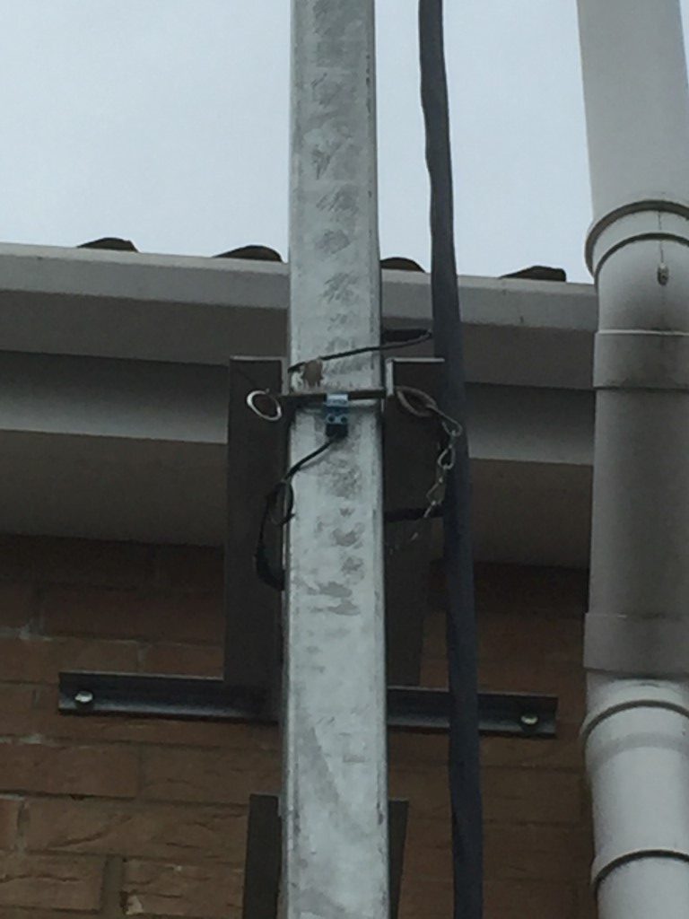
With the latest round of high winds, my wall mounted 12m mast makes a loud rattling noise which transfers into the house as the mast marginally moves within the top bracket and was getting to be a nusance.

A simple solution was to make a plastic shim to take up the small slack bewteen the mast and bracket, this is visible in the picture to the left of the pin sensor (I put a 90 degree bend in the shim so I can put it out easily).

Top mast retaining pin

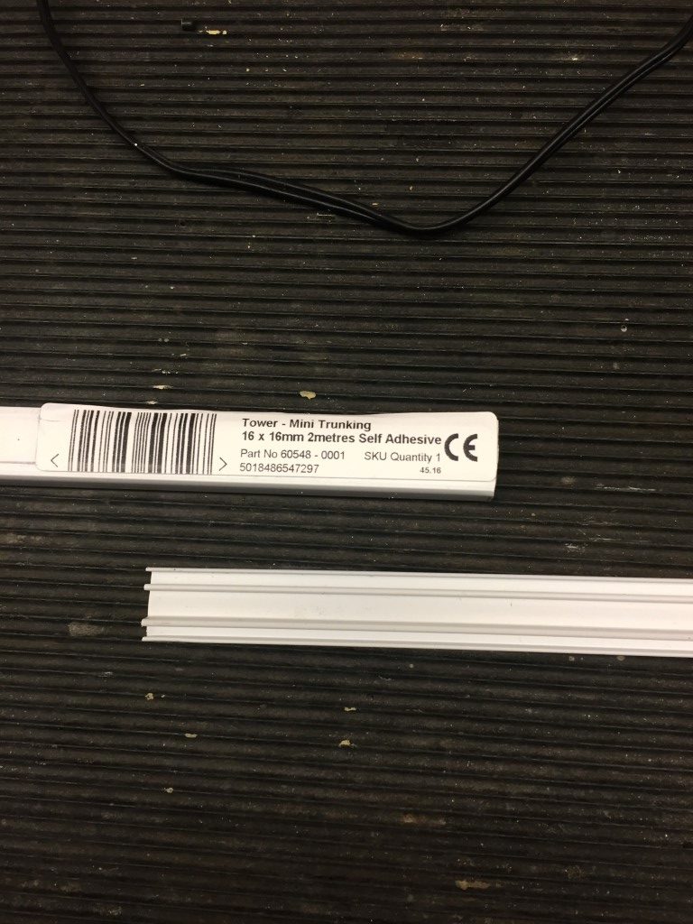
For the shim I used the a section of lid from 16 x 16 trunking lid from Screwfix.

Trunking lid

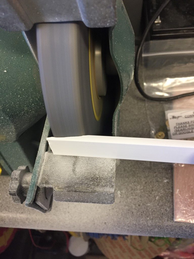
Grinding the lid lip took only a few seconds.

Trunking lid grinding down

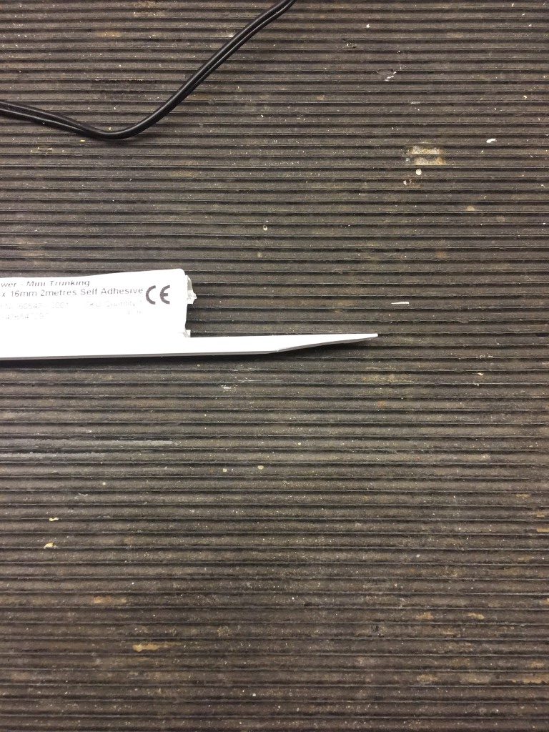
Finished shim, I used two, one between the fron pin and mast, the other to the side of the top bracket and mast, nice, cheap and easy solution which has solved the noise problem.

Finished lid for cutting

Arduino Windspeed Switch

I used to have a PC on 24/7 running weather software linked to my weather station, this allowed me to have a relay operate should the wind speed exceed a predifined value, this would then signal my antenna mast to automatically retract.

To save energy, I no longer use a PC to publish weather station data to the internet and once this was switched off I lost the relay facility, so I needed a solution.

Looking for windspeed switches on the Internet kept pointing to commercial units at £320 ish, however, I did stumble accross this link from Geeky Gadgets for an Arduino based unit which looked perfect for my needs and all credit must go to the author.

Key Parts

Mouser Electronics:

Anemometer part# 485-1733  @ £42.62

eBay:

LCD Keypad Sheild 2 x16 display 1602  @ £5.75

Arduino Uno @ £8.95

Relay unit @ £0.99

Total Cost £58.31

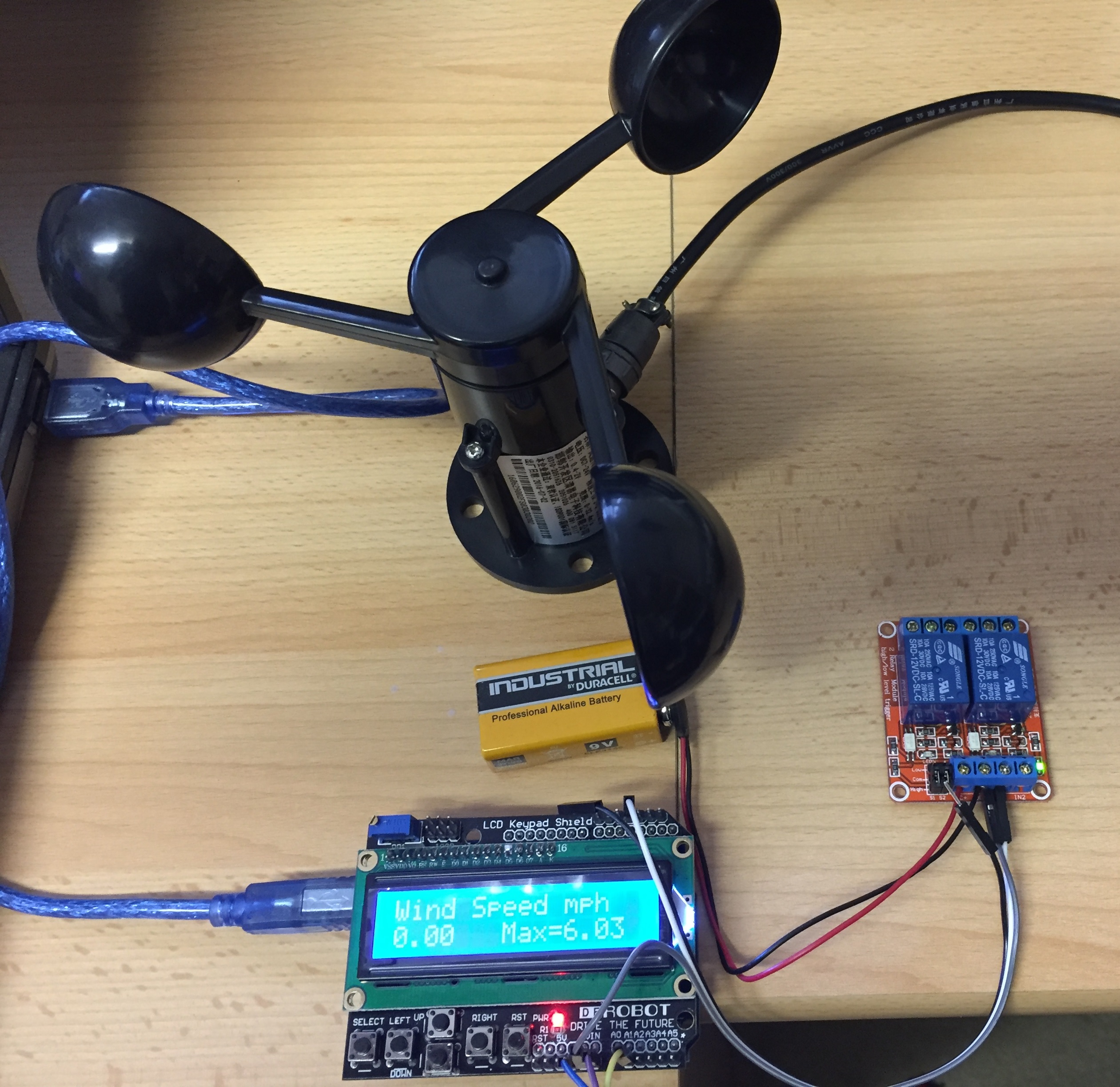
Construction was very simple, it involved plugging the LCD sheild onto the Arduino, uploading the sketch and making the three connections from the anemometer to the Arduino.

The connection information is in the Geeky Gadgets documentation with the exception of the relay output, the picture below shows this.

Things to note:

  1. The contrast pot on the LCD sheild may need to be adjusted to give an optimal display.
  2. The ‘standstill’ mV of the anemometer needs to be measured and entered in the sketch (min was 0.4345 mV) so the display shows 0 MPH at rest. This is done with a digital voltmeter to measure the resting output, or you could use trail and error and enter values in the sketch until  zero MPH is registered, and then slowly increment the values, uploading each time a change is made, until you hit a point where a speed is registered, then back the number down, at this point you should see and increase in speed displayed with minor turning of the cups.

Arduino

The above is the finished setup, just ready to mount in a suitable enclosure, for test purposes I have set the relay to operate at 4 MPH, when the speed drops below this, the relay de-energises.

The finished unit will be powered by 12v and will work as a standalone unit with a simple normally open output to the mast automation PLC.

Arduino Software can be downloaded from HERE , the working sketch which allows a replay to operate if the windspeed exceeds a preset value is below, simply copy and paste the code below into Aduino software and save the file before compiling:

===================================================

/*
Arduino Wind Speed Meter Anemometer mph – Adafruit anemometer (product ID 1733).
Modified code created March 2016 from original code created by Joe Burg 11th November 2014
At http://www.hackerscapes.com/ with help from Adafruit forum user shirad

12 Feb 17 added relay output based on wind speed.
*/

//Initialise LCD display

#include <LiquidCrystal.h>
LiquidCrystal lcd(8, 9, 4, 5, 6, 7);

int serial_in;
int relay =3;
//Setup Variables
double x = 0;
double y = 0;
const int sensorPin = A1; //Defines the pin that the anemometer output is connected to
int sensorValue = 0; //Variable stores the value direct from the analog pin
float sensorVoltage = 0; //Variable that stores the voltage (in Volts) from the anemometer being sent to the analog pin
float windSpeed = 0; // Wind speed in meters per second (m/s)

float voltageConversionConstant = .004882814; //This constant maps the value provided from the analog read function, which ranges from 0 to 1023, to actual voltage, which ranges from 0V to 5V
int sensorDelay = 2000; //Delay between sensor readings, measured in milliseconds (ms)

//Anemometer Technical Variables
//The following variables correspond to the anemometer sold by Adafruit, but could be modified to fit other anemometers.

float voltageMin = 0.4345; // Mininum output voltage from anemometer in mV.
float windSpeedMin = 0; // Wind speed in meters/sec corresponding to minimum voltage

float voltageMax = 2.0; // Maximum output voltage from anemometer in mV.
float windSpeedMax = 32; // Wind speed in meters/sec corresponding to maximum voltage

void setup()
{

//Setup LCD display with welcome screen

lcd.begin(16,2);
lcd.print(“Geeky Gadgets”);
lcd.setCursor(0,1);
lcd.print(“Windspeed Sensor”);
delay(2500);
lcd.clear();
lcd.setCursor(0,0);
Serial.begin(9600); //Start the serial connection
pinMode(relay,OUTPUT);

}

//Anemometer calculations

void loop()

{

sensorValue = analogRead(sensorPin); //Get a value between 0 and 1023 from the analog pin connected to the anemometer

sensorVoltage = sensorValue * voltageConversionConstant; //Convert sensor value to actual voltage

if (sensorVoltage <= voltageMin){ windSpeed = 0; //Convert voltage value to wind speed using range of max and min voltages and wind speed for the anemometer. Check if voltage is below minimum value. If so, set wind speed to zero.

}else { windSpeed = ((sensorVoltage – voltageMin)*windSpeedMax/(voltageMax – voltageMin)*2.23694); //For voltages above minimum value, use the linear relationship to calculate wind speed in MPH.

//Max wind speed calculation below

x = windSpeed; if (x >= y){

y = x;

}else

y = y;

}

//Print voltage and windspeed to serial

Serial.print(“Voltage: “);
Serial.print(sensorVoltage);
Serial.print(“\t”);
Serial.print(“Wind speed: “);
Serial.println(windSpeed);

//Display Wind Speed results to LCD with Max wind speed

lcd.setCursor(0,0);
lcd.print(“Wind Speed mph”);
lcd.setCursor(0,1);
lcd.print(windSpeed);
lcd.setCursor(7, 1);
lcd.print(“Max=”);
lcd.setCursor(11, 1);
lcd.print(y);
if (windSpeed >4) { //Enter the value of MPH windspeed to be exceeded which will operate the relay
digitalWrite(3,HIGH);
} else{
digitalWrite(3,LOW);

}

delay(sensorDelay);
}

===================================================

For my purposes the displayed wind speed does not have to be calibrated, I only need an indicative reading, therefore cannot vouch for accuracy of this unit.

SDRPlay and WX Satellite Decoding

Bought an SDRPlay and ‘m in the process of seeing what it will do and how it interfaces with HDSDR and Orbitron satellite tracking software, my initial aim is to receive and decode weather satellite images using WXtoImg, with operating instructions here, unfortunatly  the original WXtolmg software website is now down, but the link I’ve placed in the blog should work to an archived site where it can be downloaded.

sdr play

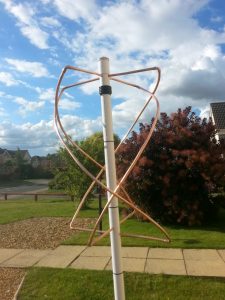
Using the excellent construction details and templates from www.askrlc.co.uk for a Quadrifiliar Helical Antenna (QFH), I had a stab at making one.

The local plumbers merchant had the 32mm waste pipe and 8mm copper pipe along with an endstop, the total value of material was £26.00.

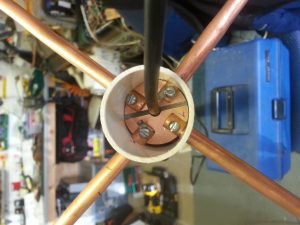
First job was to cut a piece of single sided copper board to fit in the pipe, once this was done, I cut a track in the disk as per the instructions, the dremel equivalent drill came into its own on doing this.

20160729_161139

Using the template and measurements from the website, I drill the holes for the 8mm pipe, I then used the dremel to cut a notch in the top pipe stubs the same width as the copper board, so that as I pushed each top stub in, it held the disk in place, allowing me to drill and use self tapping screws to secure the pipe in place.

20160729_174836 (Medium)

Checking with the MFJ-269C, the VSWR was 2:1 at 137.00MHz so very pleased with that.

The next step is to mount a Mini Whip on the top of the mast and get it all mounted, more info and pics will follow soon….

noaa-19-201608291343-mcir29 August 16, very first satellite download using SDRPlay and QFH antenna, lots, to tweak to get a better image, but I’m on the right track.