A good friend of mine asked is I could get him a CCTV Pan/tilt head so he could remotely control the position of his aerials which would be especially useful in the tracking of satellites, some time later I noticed that a guy was upgrading a CCTV system, I went over to him and asked I could have the scrap head, came home with it and straight onto the internet for the make and model, but more specifically the wiring details.
The one I obtained was made by Shawley Antony Ltd who are no longer trading, but the head works just fine on 24vDC with the added bonus of having electromechanical brakes for both Pan and Tilt and having potentiometers so that I can have a go at getting positional feedback displayed.
In order to make a decent project I used Ebay to get a joystick, Pulse Width Modulator motor speed control and a voltage reducer all from China at silly prices.
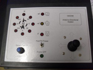
I created the personalised overlay using Visio, this allows me the layer the drawing and the dimensional drilling detail can then be used to template the drilling pattern before being turned off, and the finished overlay printed.
 Control Unit under construction
The way the controller will work is via a 24vDC supply, the 5vDC regulator will provide power to the LM3914 which will be configured for spot display of voltage derived from a potential divider circuit using the head pots, the LM3914 will drive the LEDs indicating the compass positions, I’m not sure if this will work accurately reflecting the head position, but that will be for the next part of the blog when the parts arrive. A similar arrangement will be used to drive the three LEDs showing if the head platform is at the horizontal, transitioning or vertical plane.
The switch marked Pan/Tilt Power, when operated will release the head brakes and light the associated LED, also, power will be applied to the speed controller enabling the joystick to operate the head at a variable speed set by turning the Speed Control knob, the advantage of using a pulse width modulated speed controller is that the motor does not lose torque at low speeds and will therefore not ‘stall’ under load.
 Awaiting parts to complete the controller
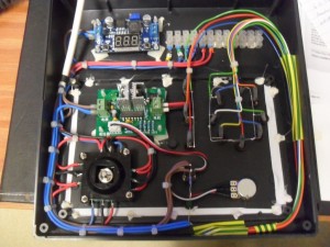
The picture shows the internal setup for the motor left/right/up/down movement which is operational, the flying leads have been attached to the LEDs ready for the next stage…Watch this space for the next installment.


Dear Sir,
It would be much easier if you were just to buy a telemetry decoder board and controller. Those pots are for telemetry fixed settings. You would be able to program in up to 50 presets and call them up at leisure. If you want more info please e-mail the above.
Best Regards,
Bob.
Hi Bob,
I agree 100% with you, to be honest it was down to cost, a controller and decoder are quite expensive and we needed a cheap but effective way of indicating rotor position, their are a number of Arduino solutions out their, so this also might be an option.
Thank you for taking the time to comment and read my blogs.
Ian
I’ll agree with Bob on this one. The best route would be to buy a pre-made telemetry controller. If you’d like to spend time learning and configuring telemetry systems, however, then you can go DIY.