I thought I’d build a test box which will simulate the three circuit conditions of an intruder detection system (IDS), these being:
- Circuit Tamper
- Alarm Condition
- Circuit Healthy or Closed (non alarm condition)
The purpose was to confirm and test the ’cause & effect’ programming of a Pyronix Euro 46 panel , the Euro 46 remote Upload/Download Software allows for logic gates to be configured, so the system ended up being very versatile.

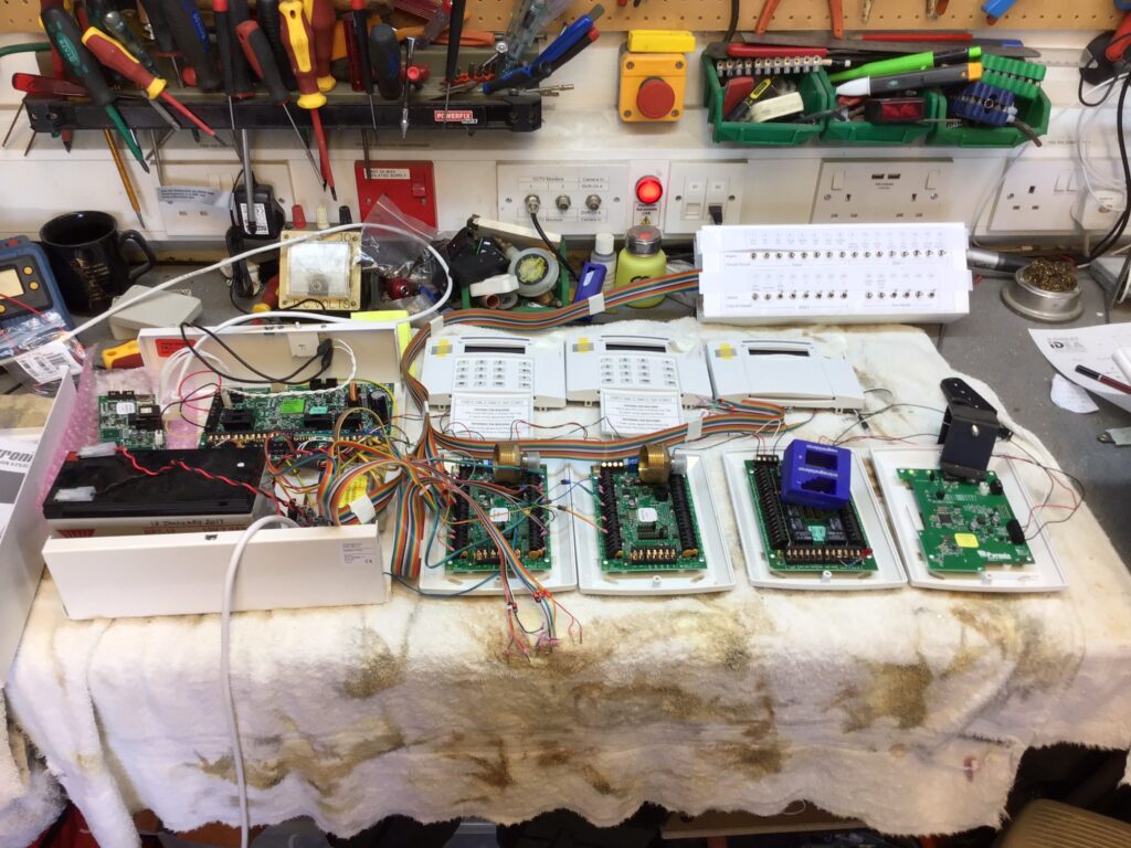
The above picture shows the Euro 46, Keypads, Zone Expansion, Output and Wireless modules set up for testing using the multiswitch test box, the alarm system is communicating with the Pyronix Cloud server via a LAN interface, cloud configuration also allows seamless integration with the Hikvision CCTV system.
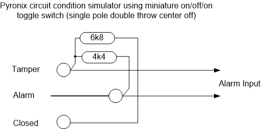
The Euro 46 has several detection circuit configurations, I chose the common value for a Double End Of Line resistor system of a 2k2 and 4k7 Ohms.
At the detection input a healthy or closed circuit, would measure a resistance value of 2k2 Ohms, if the value either exceeded or fell below this by a defined margin, the alarm panel would see this as a tamper condition, and alarm condition would present a value of 4k7 Ohms, the test box achieved the three conditions listed using the following diagram:

The above circuit presents to panel with slightly more resistance than 2k2 when healthy, however, as its within the parameters, the panel see’s this as closed with no faults.
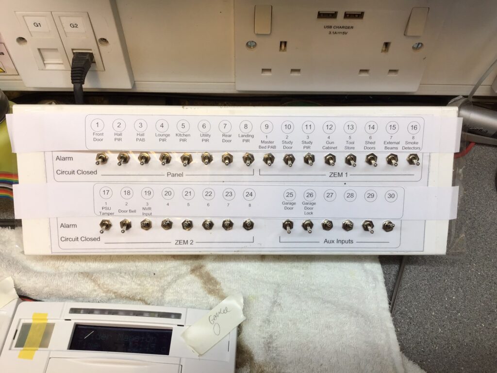
The completed unit was built using 30 switches and I utilised an old piece of trunking to fit them in:

The circuit description label temporarily sticks over the laminated switch backing so I can fully program and test the wired circuits before installation in the future, one element I can’t test is the wireless aspect which forms a a large part of this system.

