Latest Version – Modified 14 June.
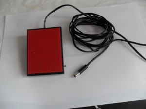
I’m slowly building up my station and thought that a foot operated ‘Push to Talk’ (PTT) would be a good addition, the switch I bought was an Eagle Electronics G028B Momentary foot switch with 6.35mm plug, this is a type used by musicians so is very robust and was bought from Juno Records for £8.41 inclusive of postage, delivery was within 2 days.
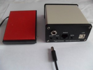
The G028B came with a 6.35mm mono jack plug, this was removed and replaced with a 2.5mm jack as the socket which is used later has a smaller footprint than a large jack socket.
The rig has two connections where it is possible to operate the PTT, the first is the microphone socket on the front of the rig, the other is using a connection available from ACC2 at the rear of the rig.
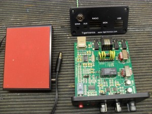
I was looking at a way of breaking into one of these cables in order to make the connection to the footswitch when I thought of using the SignaLink box as a breakout.
The SignaLink is connected to the ACC2 socket on the rig using a cable marked SLCAB13K, the connection into SignaLink is an 8 wire RJ45 plug.
The connections are (Refer to page 95 of the Kenwood instruction manual for ACC2 pin functions):
- RJ45 SignaLink 3-Kenwood ACC2
- RJ45 SignaLink 11 -Kenwood ACC2
- RJ45 SignaLink 9-Kenwood ACC2
- RJ45 SignaLink 13-Kenwood ACC2
- Not connected
- RJ45 SignaLink 4-Kenwood ACC2
- RJ45 SignaLink 8-Kenwood ACC2
- RJ45 SignaLink 12-Kenwood ACC2
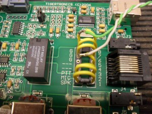
The existing SignaLink configuration links for my rig was:
- SPK
- MIC
- PTT
- — Use this to connect to Footswitch and 8.G to operate PTT
- —
- G
- G
- G
The unconnected pin 4 from the RJ45 is connected to pin 13 on the rig, this allows the PTT to operate and NOT disconnect the Mic.
I left enough lead on the footswitch socket so it will thread through the SignaLink enclose without taking the socket apart.
Removing jumper 8 out of the holder, strip a small section of insulation and solder the flying leads to the outer of the 2.5mm footswitch socket, returning the jumper to the same position as it was removed from, for the inner connection of the 2.5mm socket a wire was inserted into he empty number 4 socket on the side nearest the RJ45 socket.
This turned out to be a quick, cheap and neat workaround rather than hack into cables or adding additional plugs and sockets to make a breakout.
All done and working in under an hour, the footswitch is ‘press to make’ it does not need to be left plugged in, so can be put out of the way until needed.
Hope this was useful.


Wow! This is what I was looking for. The difference is that the footswitch operates on a sequencer, protecting the masthead preamp. The sequencer will also protect the preamp from PA power, when a PA is added later.
I was thinking about opening the 13 pin ACC2 connector in order to connect the sequencer PTT.
Was also considering connecting the sequencer PTT line direct to the mic connector. Problem is that ground is at the center pin.
I have a Signalink on the shelf – not operational yet. Have just been QRV on VHF after 35 years of QRT
Thanks for checking on my blog and commenting, glad it was of some use.
Welcome back to the hobby 🙂
All the best and stay safe