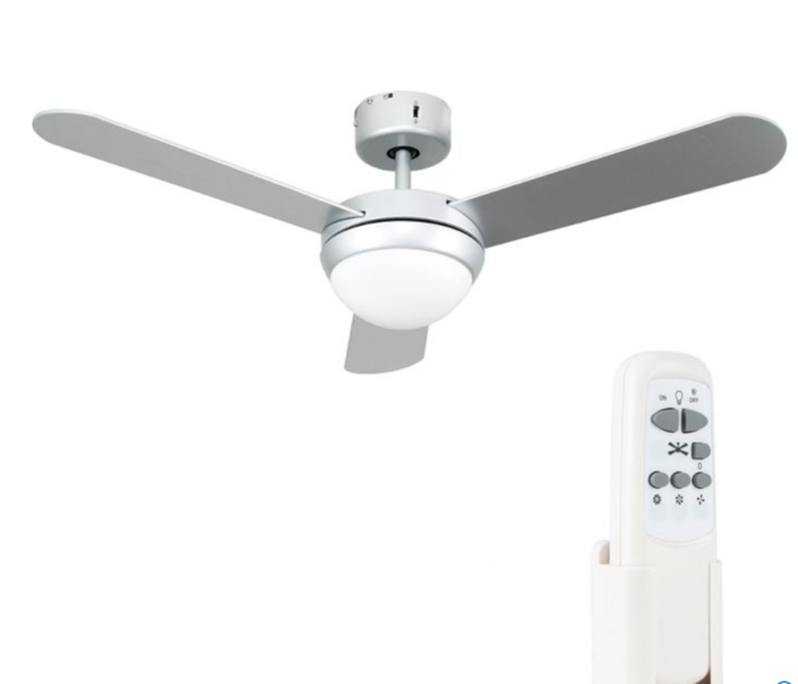
I have previously fitted a MiniSun 19500 fan and was very pleased with its performance considering the cost of the unit is quite low, however, I did have a few minor niggles relating to the lack of space in the base to fit the controller and the lack of lamp dimming.
The modifications I wanted to make were:
- Dimming of the lamps as the fan is being installed in a bedroom
- 2 way light switching i.e. switching on/off from the wall or remote control
Note: The fan I was installing was new, but out of warranty, this modification will invalidate any outstanding warranties.
What’s in the box
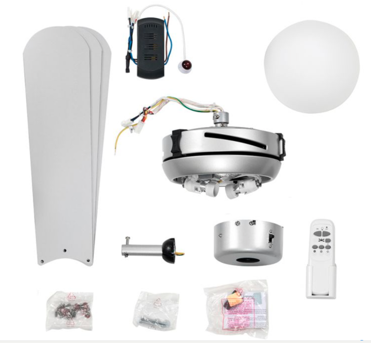
Included, but not shown above, are two, non dimmable 4W LED Golfball lamps (SES/E14).
For a standard installation, the controller uses plugs to connect to the fan motor and fan lights, with the controller then being crammed into the fan base, it is doable, but tight, so be warned.
Once power is applied, the light on/off and 3 motor speeds are selected and controlled by the remote control with the fans Infra-Red (I/R) sensor being adhered to the ceiling.

Modification
I needed to do a few enabling tasks before the ceiling fan was fitted, this meant the removal of the existing bedroom light and re-routing of the cables, also the installation of a 3 core & earth cable and Varilight V-Pro dimmer switch to replace the existing, non LED compatible dimmer switch.
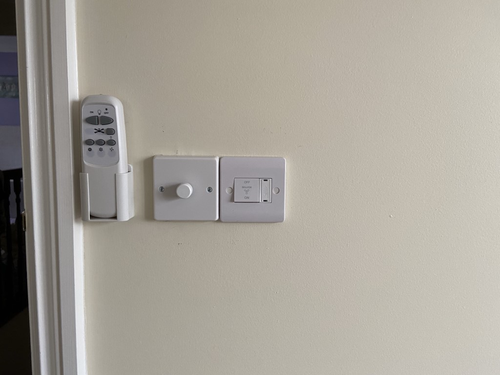
I also decided to fit a Scolmore fused isolator to make dead for maintenance, the finished arrangement is seen below:
The modification involves cutting off the controller plugs marked as 1 & 2, this allows the controller to be physically distanced from the base and reconnected using 3 core and earth cable.
The I/R Sensor wire is also cut and extended.
With the controller mounted in a suitable enclosure, a 230v AC relay is added, the relay is connected to the lamp output of the controller, and will be energized/deenergized by the light function button on the remote control.
Using the relay contacts, it is now possible to make the fan light into 2 way switching.
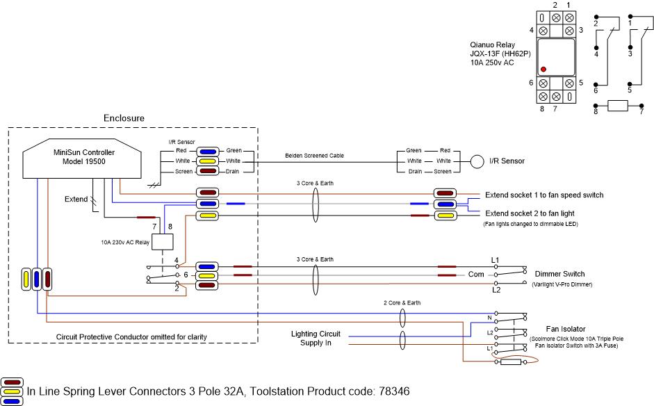
The 3 core & earth from the dimmer switch is wired across the relay contacts to enable the dimmer switch and remote control to behave as a 2 way switching arrangement with the added benefit of being able to dim the lights from the V-Pro.
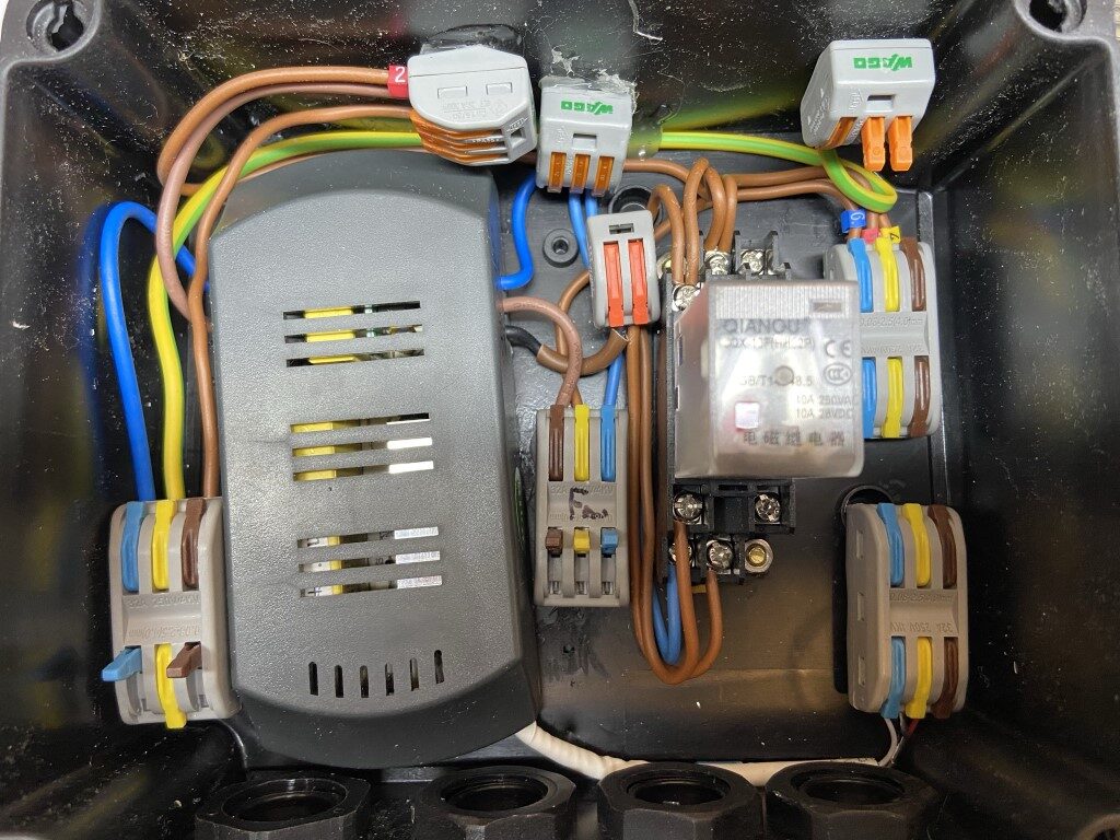
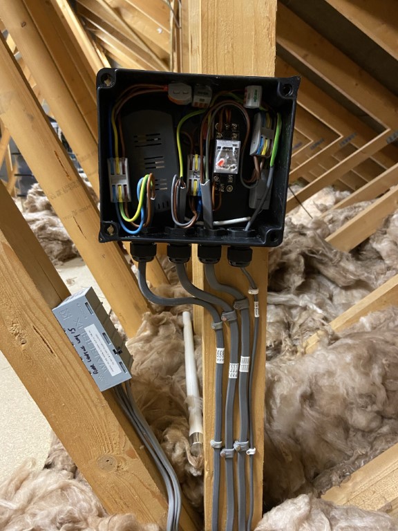
Competed project, (lid removed for picture), the maintenance free junction box (JB) to the left of the unit is where the lighting circuit Loop In & Loop Out cables have been pulled back from the original ceiling rose, the supply to the controller is from this JB via the fused isolator.

