After playing with a Programmable Logic Controller (PLC) to operate my radio mast, I decided to build a simulator in order to better understand the capabilities of the EASY PR-18DC-DA-R.
I wanted the simulator to have 16 inputs, either momentary or switched and the ability to import signals including an embedded 4 – 20mA current.
I had a sloped project enclosure already, so I made a dimensioned drilling template.

Once the template was stuck down, the pilot holes were drilled, template removed and holes opened to the right sizes.

The template was created in Visio and I used layers, one of the layers was for switch position drilling and alignment cross-hairs, turning that layer off (missed one in I8!), allowed me to print on self-adhesive sticky Matte White Vinyl.

Using a sharp knife, I cut though the Vinyl and started fitting the switches, buttons, Output indication LEDs and 4 – 20mA injector.

Terminal posts next.

Front panel populated.

Wiring started.

After a couple of changes, the internal wiring is completed and loomed in.

The simulator uses 24v DC, I used a small 1.5A output switched mode PSU for this, fed via a chassis fuse holder with the supply from an IEC male socket, the output from the PSU is fused separately.

PLC simulator all powered up, the program in the PLC was legacy from my mast control project, this will be overwritten by downloading revised programs from xLogicsoft software.

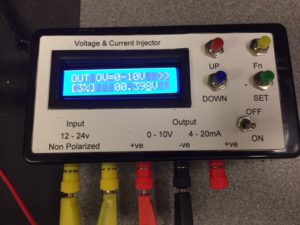
To complement the PLC simulator I bought a4-20mA Current Signal Generator 0-10V Voltage Generator Transducer Simulator for £19.00.

Injector resolution precision:
- Current 0-20mA 0.001 0.1mA
- Voltage 0-10V 0.001 0.1V


Completed test setup.

